
 English
 中文简体
中文简体 English
 Русский
 Español
 Português
 Türkçe
 العربية
 Deutsch
 Polski
 Italiano
 Français
 한국어
한국어 ไทย
ไทย Tiếng Việt
 日本語
日本語





























Automotive Power Fail Simulator
User's Manual
Applicable LISUN models: PFS-80V100A、PFS-80V150A、PFS-80V300A、PFS-80V50A
1. Basic Understanding of Equipment
1.1 Model Classification
| LISUN Model | PFS-80V50A | PFS-80V100A | PFS-80V150A | PFS-80V300A |
|---|---|---|---|---|
| Power Line Micro-Interruption Parameters | ||||
| Maximum Power Supply for the DUT | ±80 V/50 A | ±80 V/100 A | ±80 V/150 A | ±80 V/300 A |
| Key Features | Simulate conditions such as Power Line, short circuits, and plugging and unplugging | |||
| Power Switch | Built-in S1 (S+), S-, S2 | |||
| S2 Discharge Resistor | Open Circuit, 0 Ω, 0.1 Ω, 1 Ω, 100 Ω | |||
| Rising/Falling Edge Duration | <20 ns | |||
| Voltage Change Rate | >100 V/µs, ≥20 V/µs | |||
| Activation/Deactivation Time | 1 µs–16 s | |||
| Interrupt Time Step | Support | |||
| Calibration Accessories | 1 Ω, 100 Ω | |||
| Signal Line Micro-Interruption Parameters | ||||
| Key Features | Operating conditions such as interruptions and plugging/unplugging of analog signal lines | |||
| Maximum Power Supply for the DUT | ±50 V/3 A | |||
| Signal Line Channel | 16 independent channels that can be switched between | |||
| Test Mode | Supports single-channel and multi-channel simultaneous testing | |||
| Rising/Falling Edge Duration | <200 ns | |||
| Activation/Disconnection Time | 1 µs–16 s | |||
| Calibration Accessories | 1 Ω, 1000 Ω | |||
1.2 Applicable Standards
This equipment meets all or part of the requirements of the following leading domestic and international automotive electronics testing standards:
International Standards: ISO 16750-2:2023, IEC 62132-2, IEC/EN 61000-4-20, ISO 7637-2
Automotive Manufacturer Standards: Volkswagen: VW 80000; General Motors: GMW 3172; Ford: EMC-CS-2009.1, FMC 1278; BMW: GS 95003-2, GS 95024-2-1, GS 95026; DaimlerChrysler: DC-10615, DC-10842, CS-11979; Fiat: 9.90110; Hyundai/Kia: ES 95400-10, ES 96100-02, ES 39110-00; Volvo: STD 515-003; Mitsubishi: ES-X82010; Nissan: 28401; Peugeot Citroën: B21 7110; Iveco: 16-2103; Jaguar Land Rover: JLR-EMC-CS; Tesla: TS-0000425-05; Renault: 36.00.808.
Domestic Standards: Great Wall: GWT A D01-01:2020-09 “General Test Specifications for Automotive Electronic and Electrical Components”; WM Motor: Q/WM J073013A-2019; Dongfeng Motor: Q/DK TE 4601-2019; Industry Standards: LV 124, LV 148, MBN 10615, MBN LV 124-1.
1.3 Application Scenarios
The PFS Series Automotive Power Fail Simulator is a specialized test device developed and manufactured specifically to meet the testing requirements for wiring harness interruptions (micro-interruptions) in power and signal lines of automotive electronic components. The equipment can accurately simulate operating conditions encountered during actual vehicle operation—such as power line interruptions, short circuits, and plug-in/unplug-in vibrations, as well as signal line interruptions and poor contacts—providing a reproducible basis for evaluating the immunity and reliability of automotive electronic components.
2. Precautions for Use
2.1 Environmental Requirements
Ambient temperature: 23 °C ± 5 °C; relative humidity: 45–75%, non-condensing; altitude: ≤2000 m; no strong vibrations or electromagnetic interference in the surrounding area; use of the equipment in dusty, flammable, or explosive environments is strictly prohibited.
2.2 Power Supply Requirements
Input power supply: AC 220 V ±10%, 50 Hz; Input power: ≤1 kW; The power supply must be reliably grounded, with a ground resistance of ≤4 Ω; It is recommended to use a voltage-stabilized power supply to prevent power grid fluctuations from affecting test accuracy.
2.3 Wiring Principles
Use Power Line with the specified wire gauge to prevent overheating under high current conditions; keep test cables as short as possible and route them in parallel to minimize the effects of parasitic parameters; ensure that the DUT (Device Under Test) enclosure is reliably connected to the equipment’s protective ground; and route Power Line separately to avoid cross-interference.
2.4 Operational Safety Guidelines
Wear appropriate insulated protective gear; before testing, ensure that all connections are secure and that there are no exposed conductors; do not touch or plug in or unplug any wiring harnesses or cables during testing; if you hear unusual noises, smell an unusual odor, or notice smoke, disconnect the power immediately; when conducting prolonged continuous testing, ensure the equipment is properly ventilated to allow for heat dissipation.
3. Equipment Overview and Wiring
3.1 Front Panel
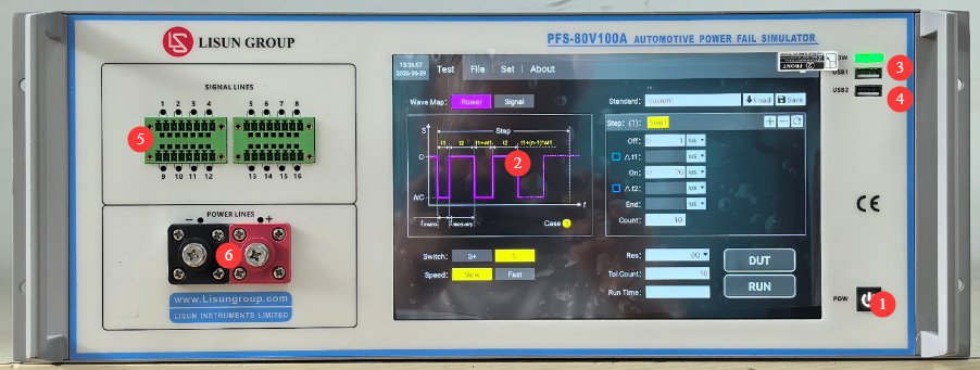
See Figure 3-1.
| Number | Note |
|---|---|
| ① | Device power switch: Press briefly to turn on; press and hold to turn off. |
| ② | 10.1-inch Capacitive Touchscreen |
| ③ | USB1 port: Used by LISUN engineers for device debugging; users do not need to use it. |
| ④ | USB 2.0 port, which can be used to connect a mouse to control the touchscreen, or to connect a USB flash drive to upgrade the software or update database files |
| ⑤ | DUT signal line interface, with a total of 16 independent signal line channels, used for micro-interrupt testing of DUT signal lines |
| ⑥ | DUT Power Line connector, used for DUT Power Line micro-interruption testing; observe polarity |
3.2 Back Panel
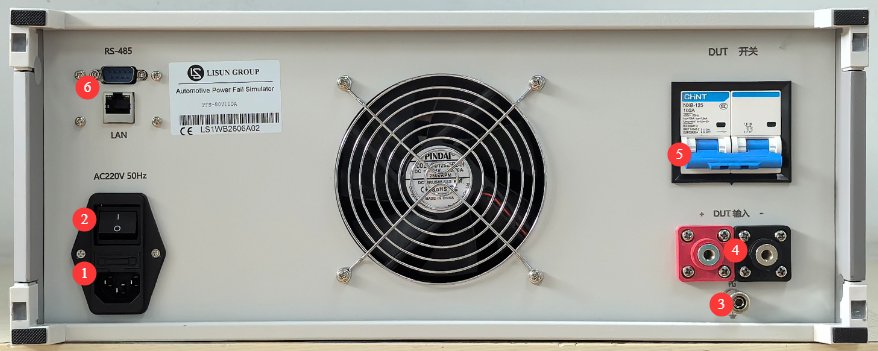
See Figure 3-2.
| Number | Note |
|---|---|
| ① | Power cord receptacle and fuse; ensure the input power supply is properly grounded |
| ② | Circuit breaker, main power switch for the input power supply for equipment |
| ③ | Protective grounding terminal: If the input power supply does not have a reliable ground connection, this terminal must be connected separately to ground. |
| ④ | DUT Power Input Connector: A suitable external power supply must be provided for the DUT. You may use LISUN’s LIS-APS series four-quadrant power supply, or another suitable DC regulated power supply appropriate for the DUT. Pay attention to polarity. |
| ⑤ | DUT Power Switch |
| ⑥ | RS485 interface/LAN port, which can be connected to a computer to use the host software (for backup purposes). The host software offers the same functionality as the touchscreen; please contact us if needed. |
3.3 Introduction to Accessories
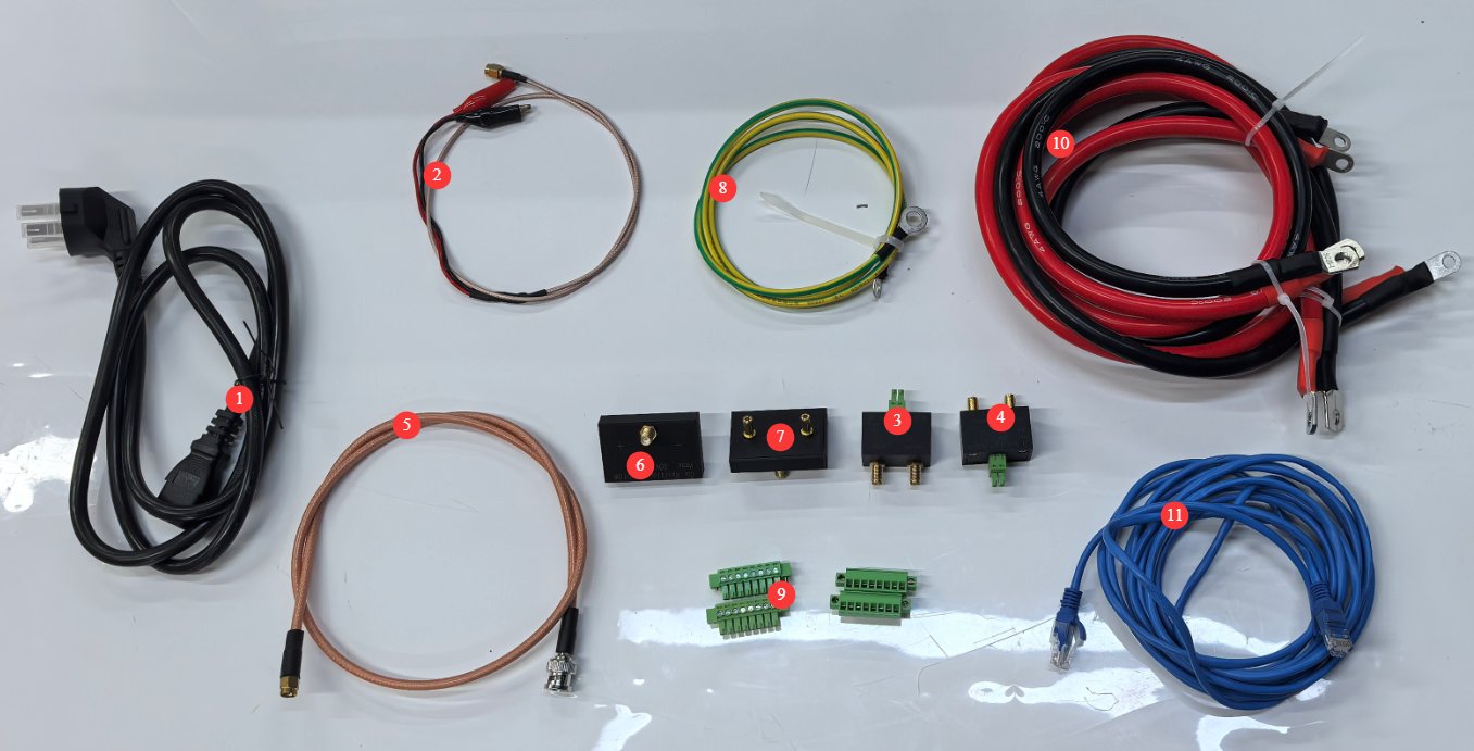
See Figure 3-3.
| Number | Note |
|---|---|
| ① | Power Line |
| ②③④ | Used to view waveforms of microinterruptions in signal lines using an external oscilloscope |
| ⑤⑥⑦ | Used to view waveforms of Power Line micro-interruptions using an external oscilloscope |
| ⑧ | Ground Wire |
| ⑨ | Signal Line Connection Module |
| ⑩ | DUT Input and Output Power Connection Cables |
| ⑪ | Ethernet cable, used to connect a computer to host software |
4. Introduction to the Touchscreen Program
4.1 Test Interface
4.1.1 Power Line Test Interface
See Figure 4-1.
| Number | Note |
|---|---|
| ① | Selecting Power Line Testing |
| ② | Click to run the device’s built-in standard tests, or select a custom test |
| ③ | Schematic Diagram of Test Waveforms |
| ④ | If you select the device’s built-in standards, all test parameters in the red-bordered areas have already been configured according to the corresponding standards and do not need to be modified; if you select “Custom Test,” you can modify the test parameters. |
| ⑤ | For custom tests, you can save the configured test parameters to the device so they can be retrieved later. |
| ⑥ | Runtime is displayed and calculated automatically; a progress bar will appear to show the test’s progress once the test begins. |
| ⑦ | DUT: Click to turn on the DUT’s power; click again to turn it off. |
| ⑧ | RUN: Once you have selected the waveform and other parameters, click this button to start the test. During the test, the progress bar updates once per second to show the current progress until the test is complete. Click this button again during the test to stop the current test. |
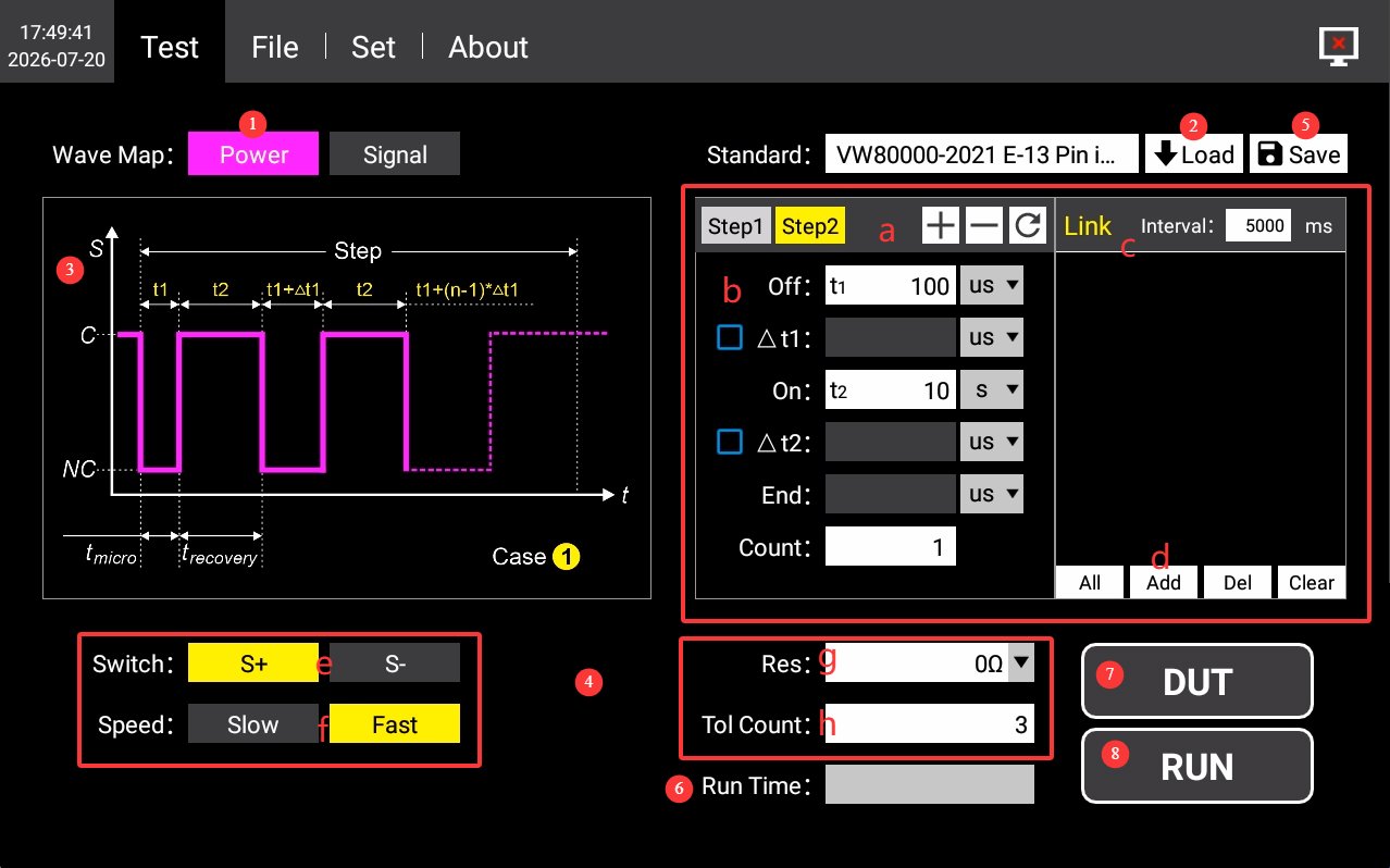
Test Parameter Overview: a) Add, delete, and reset test steps; b) Test waveform parameters, turn-off and turn-on times, step time, and number of cycles; c) Automatic linking to other test standards; d) Add or delete linked standards; e) Switch selection: S+ and S-; f) Switch speed selection: slow or fast; g) Discharge resistor S2; h) Total number of cycles.
4.1.2 Signal Line Test Interface
See Figure 4-2.
| Number | Note |
|---|---|
| ① | Select Signal Line Test |
| ② | Click to run the device’s built-in standard tests, or select a custom test |
| ③ | Schematic Diagram of Test Waveforms |
| ④ | If you select the device’s built-in standards, all test parameters in the red-bordered areas have already been configured according to the corresponding standards and do not need to be modified; if you select “Custom Test,” you can modify the test parameters. |
| ⑤ | Select the channel you want to test |
| ⑥ | For custom tests, you can save the configured test parameters to the device for future use. |
| ⑦ | Runtime is displayed and calculated automatically; a progress bar will appear to show the test progress once the test begins. |
| ⑧ | DUT: Click to turn on the DUT’s power; click again to turn it off. |
| ⑨ | RUN: Once you have selected the waveform and other parameters, click this button to start the test. During the test, the progress bar updates once per second to show the current progress until the test is complete. Click this button again during the test to stop the current test. |
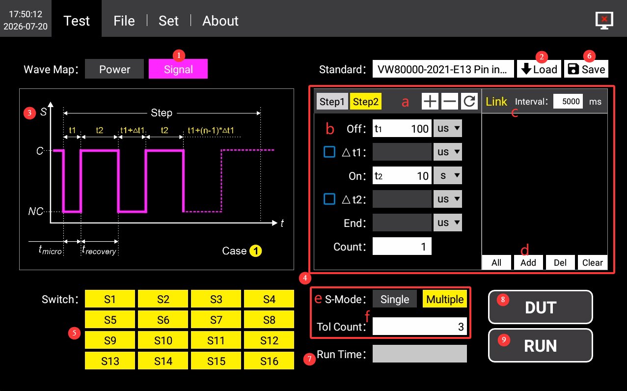
Test Parameter Overview: a) Add, delete, or reset test steps; b) Test waveform parameters, turn-off and turn-on times, step time, and number of cycles; c) Automatically link to other test standards; d) Add or delete linked standards; e) Switching mode: individually or simultaneously; f) Total number of cycles.
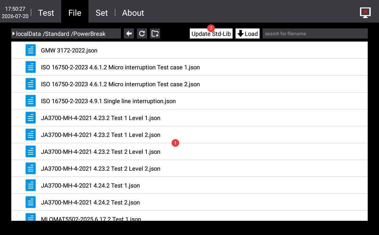
4.2 Database File Interface
See Figure 4-3.
| Number | Note |
|---|---|
| ① | Test Plan Standard Library Management. You can manage the custom test parameters you have saved; do not modify or delete the test parameters built into the device. |
| ② | If you have other standard tests but do not wish to create custom tests, please contact us and send us the detailed specifications of the relevant standards. We will guide you on how to use a USB drive to update the database file directly with those standards. |
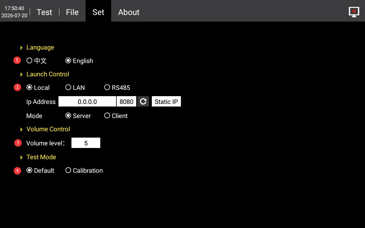
4.3 Settings Interface
See Figure 4-4.
| Number | Note |
|---|---|
| ① | Switch Between Chinese and English |
| ② | Communication settings are set to “LOCAL” by default. If you need to use host computer software, you can switch to RS485 or the LAN port. Please contact us. |
| ③ | Volume Settings |
| ④ | Test Mode: Use the default mode during testing; if you need to view micro-interrupt waveforms using an external oscilloscope, switch to Calibration Mode. |
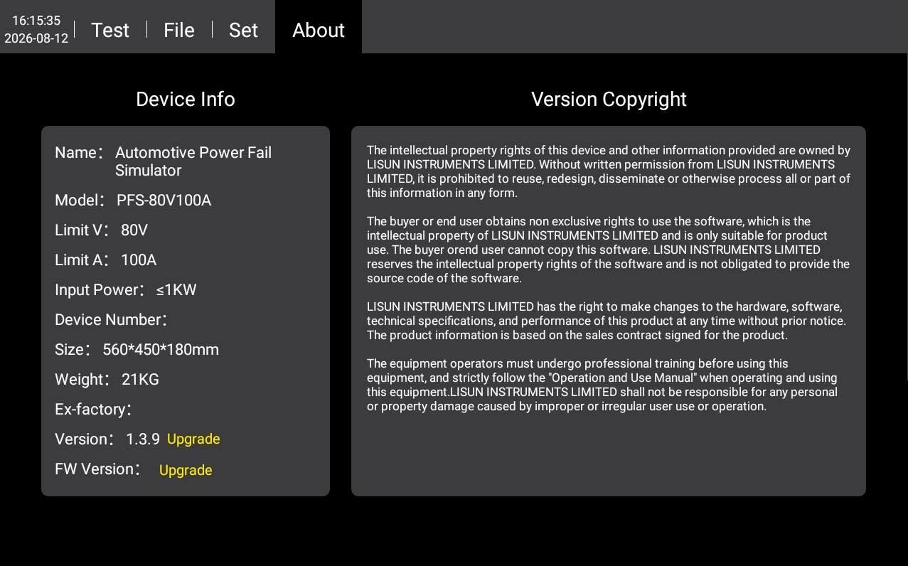
4.4 About the Interface
For device information, firmware version, and copyright notice, see Figures 4–5.
5. Procedure for Micro-Interruption Testing of Automotive Wiring Harnesses
5.1 General Operating Procedures
5.1.1 Wiring
Ensure that both the device and the DUT are powered off; use a test cable to connect the device’s DUT power cable port to the power cable of the device under test; use a cable to connect an external power supply (LIS-APS or other regulated DC power supply) to the DUT input power supply port on the back of the device; If the DUT has signal lines, connect them to the signal line channels on the device’s front panel using the dedicated terminals.
5.1.2 Parameter Settings
Set the test parameters as described in Section 4.1. Perform Power Line micro-interrupt and signal line micro-interrupt tests as needed. When performing a signal line micro-interrupt test, manually select the channel to be tested.
5.1.3 Test Execution Steps
Turn on the external power supply and check the DUT’s output; turn on the DUT power switch on the back of the device; tap the DUT button on the touchscreen to verify that the DUT is operating normally; on the touchscreen test interface, tap the RUN button to start the test; observe the DUT’s operating status and record any observations; wait for the test to complete; in case of an emergency, you may stop the test immediately.
5.2 Evaluation of Results
Take the ISO 16750-2:2023 standard as an example.
PASS Criteria: After the entire interrupt sequence has been executed, all three of the following conditions must be met: No permanent functional failures occurred during the test; transient signal fluctuations were within acceptable limits; After the interrupt ends, the DUT automatically returns to its normal operating state prior to the interrupt, without requiring manual reset or power cycle; there is no loss of stored parameters, fault records, or learned values, nor any abnormal overwriting.
Failure (FAIL) Criteria: The DUT fails if any of the following conditions occur: the DUT freezes or crashes and requires manual power cycle to recover; the communication bus remains permanently offline or continuously reports message errors; loss of data in non-volatile memory; overheating, burnout, open circuits, or short circuits in components; or output performance parameters exceeding the tolerance range specified in the standard.
5.3 Procedures at the End of the Test
Ensure that both the equipment and the DUT are powered off; disconnect the wiring on the DUT side first, then disconnect the wiring on the equipment side.
6. Daily Maintenance and Care of Equipment
6.1 Daily Cleaning
6.1.1 Cleaning Schedule and Procedures
After each use: Clean the touchscreen surface and remove dust from the device panel;
Weekly: Clean the equipment housing and the filters on the vents;
Monthly: Clean dust from inside the equipment (to be performed by a professional).
6.1.2 Cleaning Methods
Wipe the exterior with a clean, soft, lint-free cloth; use a specialized screen cleaner for the touchscreen; clean the vents with a soft-bristled brush and use a vacuum cleaner if necessary; do not use corrosive solvents such as acetone.
6.2 Regular Inspections
Check Power Line for damage or wear; check that the ground connection is secure; check that the fan is operating normally; check that the buttons and touchscreen are responsive; check the terminal blocks for oxidation or loose connections.
6.3 Storage and Handling
6.3.1 Long-Term Storage Requirements
Storage Conditions: Temperature -10°C to +50°C, humidity ≤85%; Clean the equipment and take dust-proof measures before storage; Power on the equipment once every 3 months, running it for at least 30 minutes each time; Avoid stacking or applying heavy pressure to prevent the panel from warping.
6.3.2 Precautions for Handling
Unplug all external cables before moving the device; use the original packaging and ensure it is properly cushioned and protected; keep the device upright during transport and avoid vigorous shaking; when lifting, grip the bottom and sides of the device—do not lift by the panel.
6.4 Calibration Interval Requirements
To ensure the measurement accuracy and operational reliability of the equipment, it is recommended that it be sent periodically to a qualified third-party metrology laboratory for calibration. The recommended calibration interval is 12 months. Users may determine the specific calibration interval based on frequency of use, environmental conditions, and quality system requirements.
7. Troubleshooting and Resolving Common Problems
| Fault Symptoms | Possible Causes | Procedure |
|---|---|---|
| The device won’t turn on | The input power supply main power switch on the back is not turned on, or the fuse has blown. | Turn on the input power supply switch located at the power cord receptacle on the back of the device; check the fuse, and if it has blown, replace it with a fuse of the same rating. |
| Touchscreen Malfunction After Power-On | System freeze, loose ribbon cable | If the problem persists after restarting, disconnect the power, then follow our instructions to open the device casing and check whether the touchscreen ribbon cable is loose. |
| Test Stopped Automatically Midway Through | Over-temperature protection triggered, overcurrent/overvoltage protection triggered, external power supply interruption | Check whether the equipment’s ventilation is obstructed or the ambient temperature is too high; check the DUT for short circuits or overloads; check whether the external power supply has stopped outputting power. |
| USB Drive Not Recognized | USB drive format is incompatible or capacity is too large | Use a FAT32-formatted USB drive with a capacity of no more than 32 GB; if that still doesn’t work, try a different USB drive. |
| Severe waveform distortion | S2 discharge resistor setting does not match; load inductance is too high; wiring is too long or there is a loose connection | Adjust the discharge resistor setting to improve the waveform; for inductive loads, select an appropriate discharge resistor; shorten the wiring length and ensure good contact. |
| A certain channel is not working | Channel not selected; Channel damaged; Open circuit | Verify that the corresponding channel is selected on the confirmation screen; switch channels to test and compare; check whether the wiring for the corresponding channel is conductive. |