
 English
 中文简体
中文简体 English
 Русский
 Español
 Português
 Türkçe
 العربية
 Deutsch
 Polski
 Italiano
 Français
 한국어
한국어 ไทย
ไทย Tiếng Việt
 日本語
日本語





























Lamp Start, Run-Up Time And Flicker Test System
User's Manual
Applicable LISUN models: LSRF-3
1. Basic Understanding of Equipment
1.1 Equipment Applications
1.1.1 Flicker Testing
Requires use with LISUN’s Integrating Sphere/Goniophotomoeter darkroom, DC power supply, and Standard Light Source; Existing customers can also use it directly with the LPCE-2 or LPCE-3 Integrating Sphere systems or the LSG-6000/LSG-1890B/LSG-1800A Goniophotomoeter systems.
Automatically detects parameters such as flicker frequency, flicker percentage, flicker index, modulation depth, SVM, Mp, Pst, and others; automatically classifies stroboscopic light as “no risk,” “low risk,” or “high risk” in accordance with IEEE 1789.
1.1.2 Starting the Rise Time Test
The LSRF-3 must be used in conjunction with LISUN’s LSP series of precision AC variable-frequency voltage stabilizers with trigger functionality, or the LSP-Pst series AC variable-frequency power supply (IEC-Pst special edition), which fully complies with the lamp startup test method specified in Section 11.4 and the lamp ramp-up test method specified in Section 11.5 of the U. S. Energy Star V2.1 guidelines, as well as the test requirements in Table 13 of SASO 2902.
Can automatically detect: startup time, rise time.
1.2 Equipment Configuration Verification
1.2.1 Unpacking
When unpacking the device, handle it gently to avoid scratching the casing with sharp tools. After unboxing, first inspect the exterior of the device to ensure there is no visible deformation or dents, and that the buttons are not damaged or loose. If you notice any abnormalities with the device or its accessories, do not turn it on. Please contact us immediately.
1.2.2 Main Unit and Accessories
See Figure 1-1.
| Number | Note |
| ① | LSRF-3 Main Unit |
| ② | Power Adapter |
| ③ | Luminance Probe |
| ④ | Trigger cable, used to connect to LISUN AC power supplies with a trigger function |
| ⑤ | Probe connection cable, used to connect the main unit to the photometer probe |
| ⑥ | Temperature and humidity probe, used to measure temperature and humidity in a laboratory |
| ⑦ | USB cable, used to connect the console to a computer |
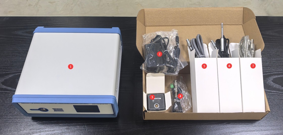
Figure 1-1
1.2.3 Downloading Electronic Documents
We have already sent you the download links for the electronic user manual, software, warranty card, and other materials via email at the time of shipment. Please download them as soon as possible. If you have not received the email, please contact us to request the download links again.
2. Precautions for Use
2.1 Electrical Safety
Before connecting the power cord, verify that the supply voltage is AC 220 V ±10% and the frequency is 50 Hz or 60 Hz. You must use a three-prong outlet with a protective ground, with a protective ground resistance of ≤4 Ω. Never cut or disconnect the protective ground wire, as doing so poses a risk of electric shock.
2.2 Environmental Safety
Do not use in environments with flammable or explosive substances, strong electromagnetic interference, high temperatures and humidity, or excessive dust levels. Operating environment: Temperature 18°C to 30°C, humidity 35% RH to 75% RH.
2.3 Operating Procedures
Low-light tests must completely block out stray light; Integrating Sphere must be sealed and free of light leaks. For darkroom tests, ensure that the probe is directly facing the light source and that there are no interfering reflective light sources in the surrounding area. Test samples must be placed in a stationary position to avoid fluctuations in light output caused by vibration. As the unit contains low-voltage precision components, do not disassemble the main unit’s casing without authorization.
3. Equipment Overview and Wiring
3.1 Introduction to the Equipment Front Panel
See Figure 3-1.
| Number | Note |
| ① | Power Switch |
| ② | Equipment Status Indicator Lights |
| ③ | Touchscreen. Note: All device operations are performed by computer software; no interaction with the touchscreen is required. |
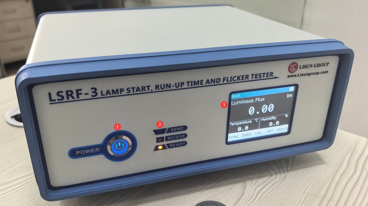
Figure 3-1
3.2 Wiring the LSRF-3 Host to the LSP Series Power Supply
See Figure 3-2.
| Number | Note |
| ① | Connect the main unit to the computer using a USB cable to enable software communication and power the device via the USB cable. Note: You may also connect the included power adapter at the same time to ensure the device continues to function properly even if the USB power supply is unstable. |
| ② | Connect the temperature and humidity probe; place the sensor in an unobstructed area of the laboratory to measure the ambient temperature and humidity. |
| ③ | Connect the photometric probe; connect the probe end to Integrating Sphere or a darkroom. |
| ④ | Connect the trigger wire; connect the other end to the LSP series power supply. |
| ⑤ | Connect the trigger wire; connect the other end to the LSRF-3. |
| ⑥ | Connect the RS-232 communication cable; connect the other end to a computer or to a computer via an RS-232-to-USB adapter cable. |
| ⑦ | Plug in Input power supply cord to connect the LSP to Input power supply |
| ⑧ | Output power connector; connect to the sample to supply power to it |
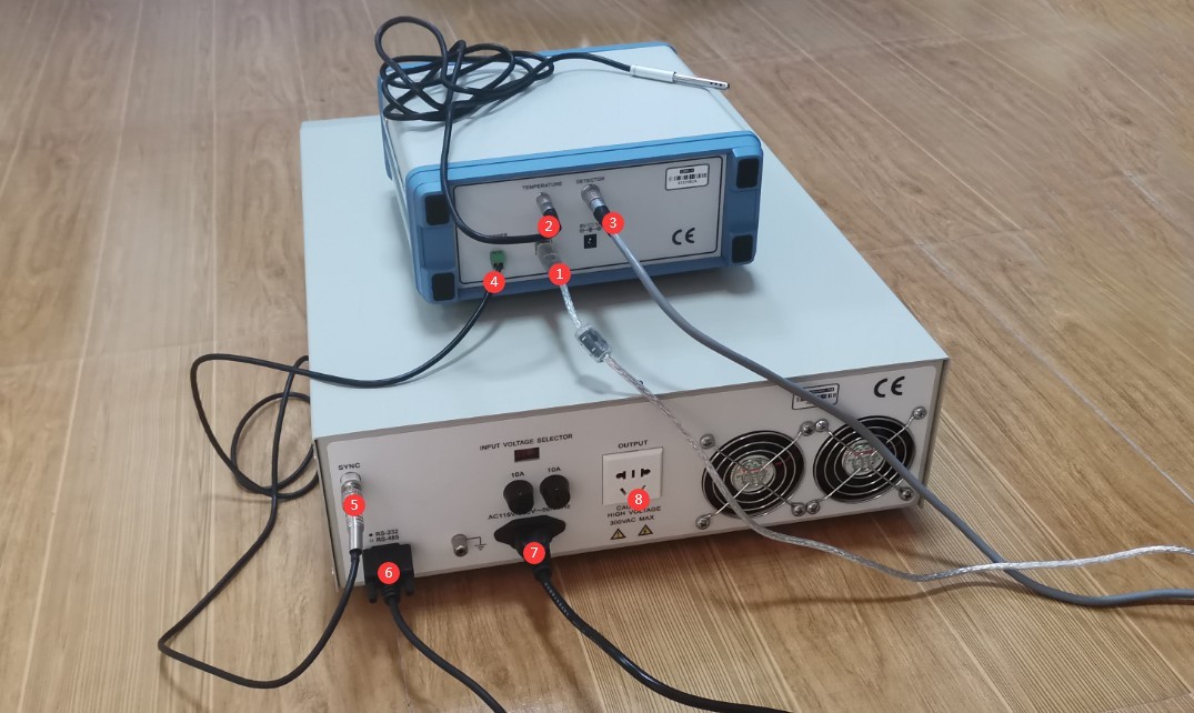
Figure 3-2
Note: If an LSP series power supply is not configured, there is no need to connect the trigger line; however, rise time tests cannot be performed, nor can the power supply output be automatically controlled via software.
3.3 Connecting the Photometric Probe
3.3.1 Integrating Sphere Scenario
When used with Integrating Sphere, see Figure 3-3.
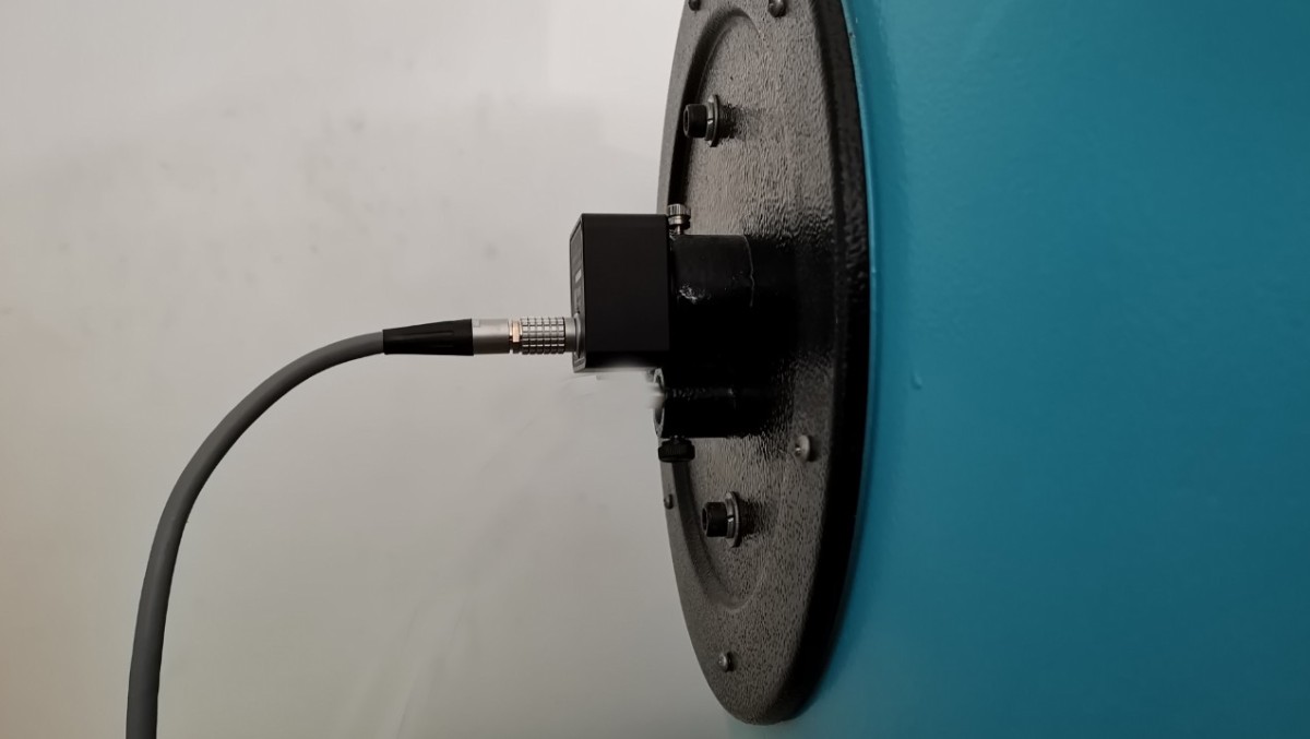
Figure 3-3
3.3.2 Darkroom Scenes
When using the device in a darkroom, use the standard probe holder to fix the probe’s orientation so that it is directly aligned with the center of the light source being measured, as shown in the schematic in Figure 3-4.
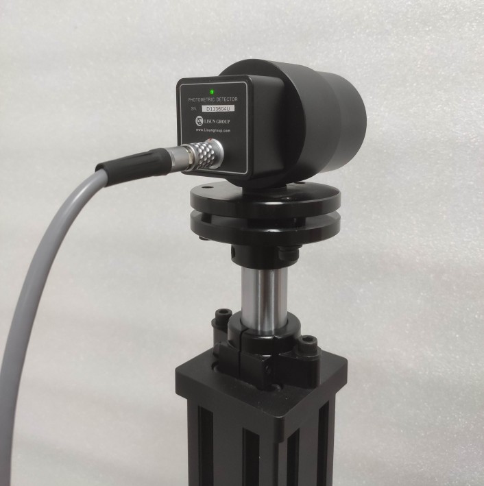
Figure 3-4
4. Software Overview
4.1 Software Installation
Software Runtime Environment: Windows 7 or later.
See Figure 4-1 for the software installation package.
| Number | Note |
| ① | LSRF-3 Software Installer—please double-click to install |
| ② | LSRF-3 Device Driver—Double-click to install |
| ③ | If the LSP series power supply is connected to a computer via an RS232-to-USB adapter cable, you will also need to install the USB adapter driver. |

Figure 4-1
4.2 Introduction to Stroboscopic Testing Software
See Figure 4-2.
| Number | Note |
| ① | Files: New, Open, Save, Save As, Export/Import CSV/TXT files, Print, Print Preview, Exit |
| ② | Settings: System Configuration, Product Information, Photometric Calibration |
| ③ | Testing: Single Test, Continuous Test, Batch Test, Stop Test |
| ④ | Help: Software Version Number, Switch Between Chinese and English |
| ⑤ | New: Create a new blank test file in .lsfx format |
| ⑥ | Open: Open a saved test file in .lsfx format |
| ⑦ | Save: Save the current file settings |
| ⑧ | Print Test Report |
| ⑨ | Product Information |
| ⑩ | System Configuration |
| ⑪ | Photometric Calibration |
| ⑫ | Single Test |
| ⑬ | Continuous Testing |
| ⑭ | Batch Test |
| ⑮ | Stop Testing |
| ⑯ | Software Version Number |
| ⑰ | X-axis: Time; Y-axis: Luminous flux |
| ⑱ | Horizontal axis time range. Enter manually and confirm; Auto-select: The software automatically selects a range; Show All |
| ⑲ | Click the “Standards” tab to view the test spectra for the corresponding standards. |
| ⑳ | All test information and test result data are displayed |
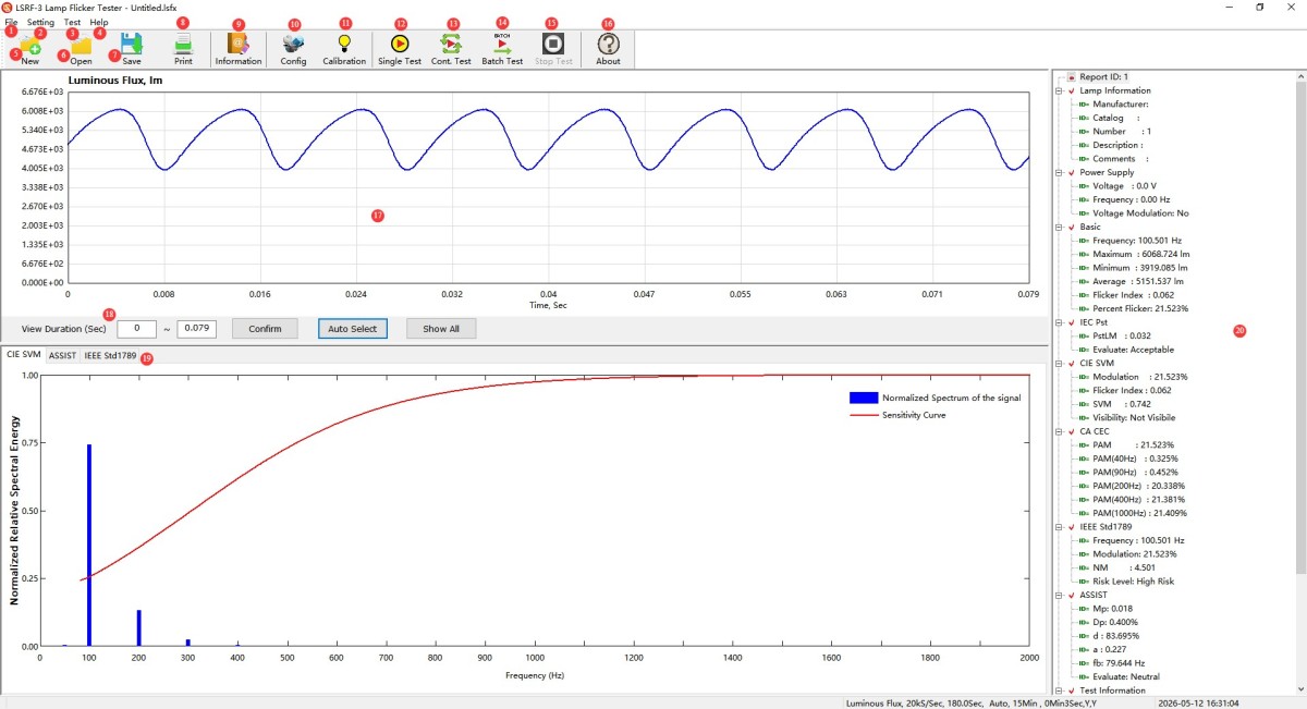
Figure 4-2
4.3 Introduction to the Start-Up and Ramp-Up Test Software
See Figure 4-3.
| Number | Note |
| ① | File: New, Open, Save, Save As, Export to CSV/TXT, Print, Print Preview, Exit |
| ② | Settings: System Configuration, Test Settings, Product Information, Criteria Settings, Photometric Calibration |
| ③ | Test: Test, Stop Test |
| ④ | Help: Software Version Number, Switch Between Chinese and English |
| ⑤ | New: Create a new blank test file in .lsrx format |
| ⑥ | Open: Open a saved test file in .lsrx format |
| ⑦ | Save: Save the current file settings |
| ⑧ | Print Test Report |
| ⑨ | Product Information |
| ⑩ | System Configuration |
| ⑪ | Test Setup |
| ⑫ | Photometric Calibration |
| ⑬ | Test |
| ⑭ | Stop Testing |
| ⑮ | Software Version Number |
| ⑯ | Time-course plot; horizontal axis: time; vertical axis: luminous flux |
| ⑰ | Horizontal axis time range: Manually enter and confirm, auto-select, or display all; Get start time: Click to automatically retrieve the start time; Custom start time: Not recommended |
| ⑱ | Rise-time graph; horizontal axis: time; vertical axis: luminous flux |
| ⑲ | Horizontal axis time range: Manual entry followed by confirmation, automatic selection, or “Show All”; Calculate rise time: Click to automatically calculate the start time; Custom rise time: Not recommended |
| ⑳ | Test information shows |
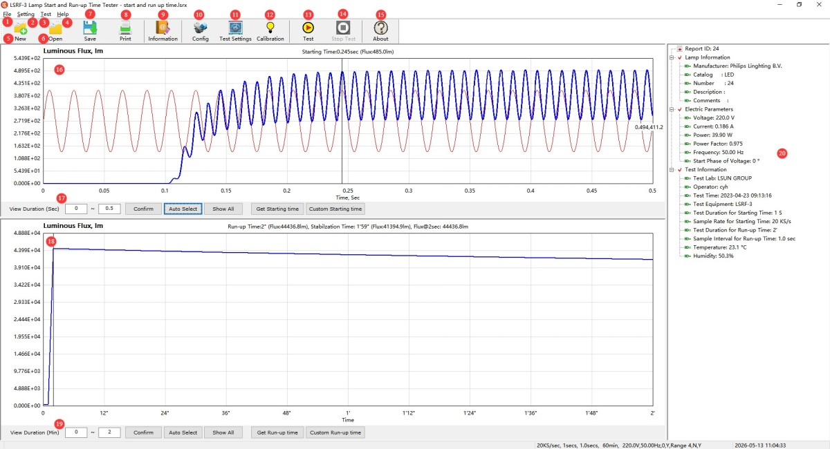
Figure 4-3
5. Steps for Stroboscopic Testing
5.1 System Configuration Settings
5.1.1 Communications
See Figure 5-1.
| Number | Note |
| ① | Connection Type: Select USB |
| ② | Device Serial Number: Automatically retrieved by the software |
| ③ | Photometric Type: Select “Luminous Flux” when using with Integrating Sphere; select “Illuminance” or “Luminous Intensity” when using in a darkroom. |
| ④ | Test Distance: Enter the correct test distance when using the device in a darkroom; this parameter is not applicable when using the device with Integrating Sphere. |
| ⑤ | AC Power Supply Model: If you have purchased an LISUN LSP Series or LSP-PST Series AC power supply, select the correct model |
| ⑥ | AC Power Communication Port: Select “Auto” to automatically detect the port. |
| ⑦ | Once you’ve finished configuring everything, click “OK” to save and exit. |
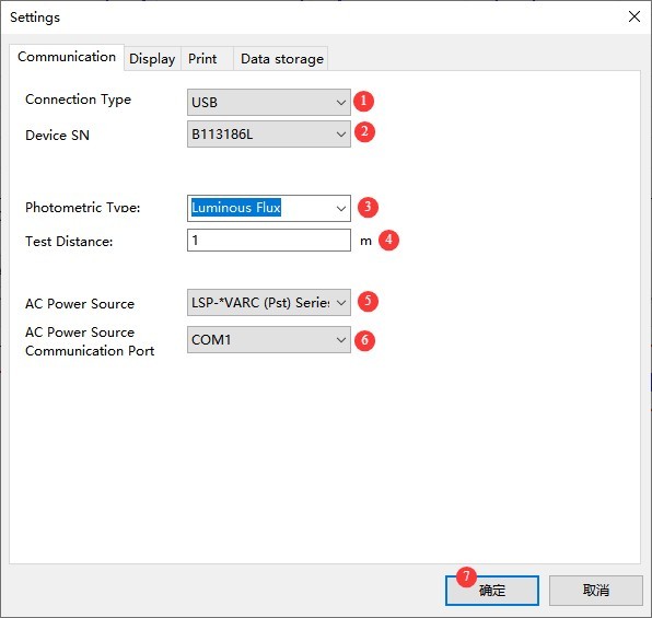
Figure 5-1
5.1.2 Display
See Figure 5-2.
| Number | Note |
| ① | Waveform display range after data is loaded: Select either “Auto” or “All” |
| ② | Number of Automatic Display Cycles: When “Automatic” is selected, the number of stroboscopic cycles the software automatically captures |
| ③ | The starting point on the vertical axis is always 0: You can check or uncheck this box as needed. |
| ④ | CIE SVM Graph Display: “Weighted Relative Spectral Energy” is selected by default |
| ⑤ | ASSIST Graph Display: “Spectral Perceptible Flicker” is selected by default |
| ⑥ | Minimum frequency: 5 Hz (default) |
| ⑦ | Once you’ve finished configuring everything, click “OK” to save and exit. |
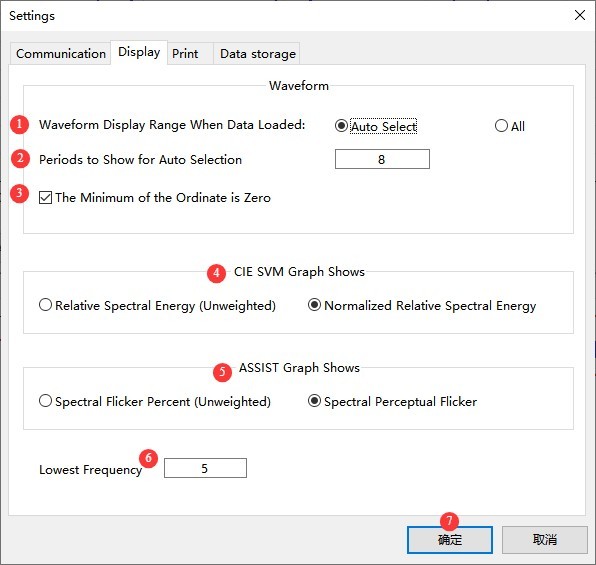
Figure 5-2
5.1.3 Printing
See Figure 5-3.
| Number | Note |
| ① | Language Selection: Chinese or English |
| ② | Report Content Selection |
| ③ | Waveform Capture Range Selection: Auto, All, Match Current Display |
| ④ | Header Settings |
| ⑤ | Should a divider line appear below the header? |
| ⑥ | Once you’ve finished configuring everything, click “OK” to save and exit. |
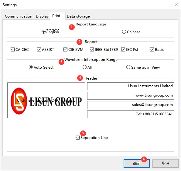
Figure 5-3.
5.1.4 Storage
See Figure 5-4.
| Number | Note |
| ① | Whether to enable auto-save for test files; we recommend checking this box |
| ② | File Save Location |
| ③ | File Naming Conventions |
| ④ | Enable automatic saving of test parameters to a list file. We recommend checking this box. |
| ⑤ | File Save Location |
| ⑥ | Enter the file name. The file format must be .csv. |
| ⑦ | Once you’ve finished configuring everything, click “OK” to save and exit. |
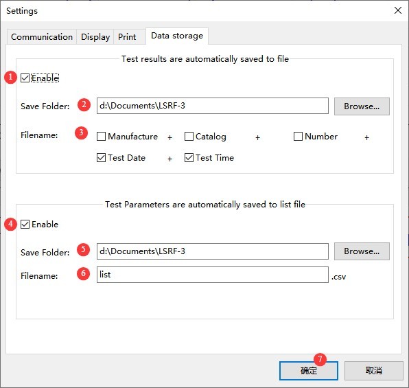
Figure 5-4
5.2 Photometric Calibration
5.2.1 Calibration Procedure
As shown in Figure 5-5, the calibration procedure is as follows.
| Number | Note |
| ① | Integrating Sphere: Ensure there is no light inside Integrating Sphere, and close Integrating Sphere; Darkroom: Ensure there is no light inside the darkroom, and close it. Then click “Zero Calibration,” wait for the software to indicate that zero calibration was successful, and confirm to exit. |
| ② | Integrating Sphere: Select “luminous flux”; Darkroom: Select “illuminance” |
| ③ | Integrating Sphere: Install the Standard Light Source exactly at the center of the Integrating Sphere and turn it on; close the Integrating Sphere and enter the luminous flux of the Standard Light Source; Darkroom: Mount the Standard Light Source on the Goniophotomoeter and turn it on. Rotate the Goniophotomoeter so that the Standard Light Source is directly facing the LSRF-3 photometric probe. Close the darkroom and enter the illuminance value of the Standard Light Source. |
| ④ | We recommend waiting 10 to 15 minutes for Standard Light Source to stabilize, then clicking “Calibrate.” |
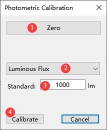
Figure 5-5
5.2.2 Calibration Frequency
Failure to calibrate does not affect the stroboscopic test results, but photometric data such as luminous flux may be inaccurate. If you wish to obtain accurate photometric data (such as luminous flux) or if you find that the photometric data is inaccurate, you can perform a calibration.
5.3 Preparations
5.3.1 Installing Lights
| Scene | Note |
| Integrating Sphere | Install the luminaire under test at the center of Integrating Sphere, and close Integrating Sphere |
| Darkroom | Mount the luminaire under test on the Goniophotomoeter, rotate the Goniophotomoeter so that its light-emitting surface faces the probe, and close the darkroom. |
5.3.2 Reference for Sampling Parameters Under Different Standards
| Applicable Standards | Sampling Rate | Sampling Time |
| CA CEC | ≥20 kS/s | ≥1 s |
| CIE SVM | ||
| ASSIST | ≥10 kS/s | ≥2 s (≥10 s for unstable light sources) |
| IEC-Pst | ≥180 seconds | |
| Energy Star V2.1 | ≥10 kS/s (Pst/Mp), ≥20 kS/s (all others) | ≥180 s (Pst/Mp) |
| IEEE Std 1789 | ≥2 kS/s | ≥ 8 cycles of the signal under test |
| BASIC | ≥10 kS/s | ≥5 seconds |
When performing the Pst LM (I) test in accordance with IEC TR 61547-1 (IEC-Pst), you must select one of the five built-in sets of modulation frequencies and fluctuation percentages provided by the software; custom settings are not permitted. Modulation is not required for other tests or other standards.
5.4 Start Testing
5.4.1 Single-Test/Continuous-Test Interface
See Figures 5–6.
| Number | Note |
| ① | If you select “Unmodulated,” enter the Input power supply voltage and frequency for the sample luminaire. |
| ② | If you select “Pst Power Modulation Mode,” choose the Input power supply voltage and frequency for the test luminaire, and then select the modulation ratio . Note: This feature requires a LISUN LSP-PST series AC power supply. |
| ③ | Click “Output” to control the power supply output. Check the boxes for “Automatically output at the start of the test” and “Stop output at the end of the test” to allow the software to automatically control the power supply output . Note: This feature requires a LISUN LSP/LSP-PST series AC power supply. |
| ④ | Sampling Rate Settings |
| ⑤ | Sampling Time Settings |
| ⑥ | To set the measurement range, simply select “Auto Range.” |
| ⑦ | Warm-up Time Setting: This setting is used to test the flicker data of the lighting fixture in a stable state. After clicking “Start,” the software begins a countdown, and the test will run automatically once the countdown ends. |
| ⑧ | Interval setting—applies only to continuous testing, i.e., the interval between two consecutive tests |
| ⑨ | Use trigger-based testing; this is a backup feature—please do not check this box. |
| ⑩ | Once everything is set up, click OK to start the test. |
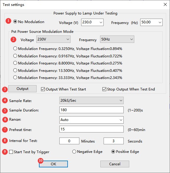
Figures 5–6
Note: During continuous testing, all reports will be automatically saved according to the settings in 5.1.4.
5.4.2 Batch Testing Interface
See Figures 5–7.
| Number | Note |
| ① | Select a sample light fixture and enter the Input power supply voltage |
| ② | Check the “Stop Output at End of Test” box, and the software will automatically turn off the power output when the test ends. |
| ③ | Whether modulation is required at 50 Hz and the modulation ratio; these options can be selected in bulk |
| ④ | Whether modulation is required at 60 Hz and the modulation ratio; these options can be selected in bulk. |
| ⑤ | Test Intervals for Different Modulations |
For other settings, see Section 5.3.2.
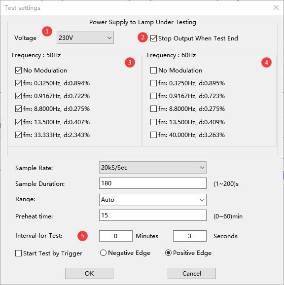
Figure 5-7
Note: For batch testing, all reports will be automatically saved according to the settings in 5.1.4.
5.5 Viewing Test Reports
Refer to Section 4.2 to open the “Product Information” screen and enter the information, as shown in Figure 5-8.
| Number | Note |
| ① | Enter reports, products, and test information |
| ② | The software automatically measures the temperature and humidity of the test environment. |
| ③ | Reports, Auto-Increment Feature for Product Numbers |
| ④ | Once you have filled in and configured all the settings, click “OK” to save and exit. |
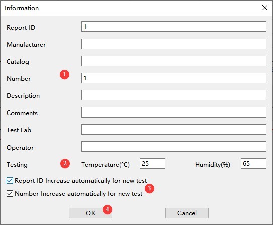
Figure 5-8
Then, following the instructions in Section 4.2, print the test report or export the test data.
6. Steps for Performing the Start-up Rise Time Test
6.1 System Configuration Settings
6.1.1 Configuration
See Figure 6-1.
| Number | Note |
| ① | Select model LSRF-3; the software will automatically retrieve the serial number. |
| ② | Select the AC power supply model and choose “Auto Detect” for the port; the software will automatically detect the communication port. |
| ③ | The options “Automatically Turn On Power” and “Automatically Turn Off Power” are checked by default. The software must automatically control the power supply to run the ramp-up test; otherwise, the test cannot be performed. |
| ④ | For the sync signal, “Rising Edge Trigger” is selected by default; “Falling Edge Trigger” is a backup function that is currently unavailable—please do not select it. |
| ⑤ | Custom Observation Points for Rise Characteristics: You can enter a specific time to view the luminous flux value at that moment. |
| ⑥ | To display the voltage waveform in the characteristic waveform display window when it is launched, you can check or uncheck this box as needed. |
| ⑦ | Once you’ve finished configuring everything, click “OK” to save and exit. |
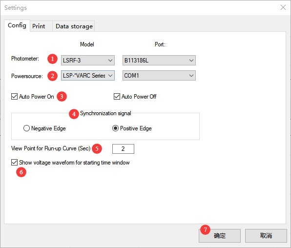
Figure 6-1
6.1.2 Printing
See 5.1.3; the functionality is the same.
6.1.3 Storage
See Section 5.1.4; the functionality is the same.
6.2 Photometric Calibration
6.2.1 Calibration Procedure
See Figure 6-2; the calibration procedure is as follows.
| Number | Note |
| ① | Integrating Sphere: Ensure there is no light inside Integrating Sphere, and close Integrating Sphere; Darkroom: Ensure there is no light inside the darkroom, and close it. Then click “Zero Calibration,” wait for the software to indicate that zero calibration was successful, and confirm to exit. |
| ② | According to the standard, luminous flux must be used as a reference for all rise time tests; therefore, whether using Integrating Sphere or a darkroom, calibration must be performed using luminous flux. |
| ③ | Integrating Sphere: Install the Standard Light Source exactly at the center of the Integrating Sphere and turn it on; close the Integrating Sphere and enter the luminous flux of the Standard Light Source; Dark Chamber: Mount the luminaire under test on the Goniophotomoeter and turn it on; rotate the Goniophotomoeter so that its light-emitting surface faces the LSRF-3 photometric probe; close the dark chamber; enter the luminous flux of the luminaire under test. |
| ④ | We recommend waiting 10 to 15 minutes until the light source stabilizes, then clicking “Calibrate.” |
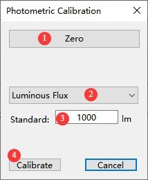
Figure 6-2
6.2.2 Calibration Frequency
Failure to calibrate does not affect the results of the startup rise time test, but the photometric data will be inaccurate. If you want to obtain accurate photometric data, such as luminous flux, or if you find that the photometric data is inaccurate, you can run a calibration.
6.3 Preparations
6.3.1 Installing Lights
| Scene | Note |
| Integrating Sphere | Install the luminaire under test at the center of Integrating Sphere, and close Integrating Sphere |
| Darkroom | Mount the luminaire under test on the Goniophotomoeter, rotate the Goniophotomoeter so that its light-emitting surface faces the probe, and close the darkroom. |
6.3.2 Setting Criteria
Refer to Section 4.3 to access the criteria settings interface, as shown in Figure 6-3.
| Number | Note |
| ① | Define the startup time as a percentage; for example, based on Energy Star guidelines, you can set it to 98%. |
| ② | Defining the Start Time Based on Peak Values |
| ③ | Customizable; please contact us if you have any other customization requests. |
| ④ | Define the rise time as a percentage; for example, based on Energy Star guidelines, it can be set to 80%. |
| ⑤ | Definition of lamp stability: For example, within the specified stabilization period of 15 minutes, the fluctuation in light output does not exceed 1%. |
| ⑥ | Once you’ve finished configuring the settings, click OK to save and exit. |
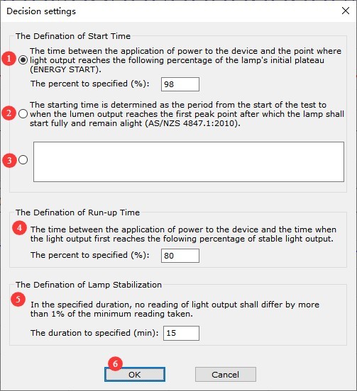
Figure 6-3
6.4 Start Testing
Click “Test” to open the test settings screen, as shown in Figure 6-4.
| Number | Note |
| ① | Set the power output parameters: voltage, frequency, and initial phase angle of the supply voltage |
| ② | Click to automatically select the correct range |
| ③ | Start Time Test Parameter Settings: Sampling Duration, Sampling Rate |
| ④ | If you need to test the rise time at the same time, check the “Test Rise Time” box, and then set the test parameters: rise time test duration and rise time test interval. |
| ⑤ | Once you’ve finished configuring the settings, click “OK” to start the test automatically. |
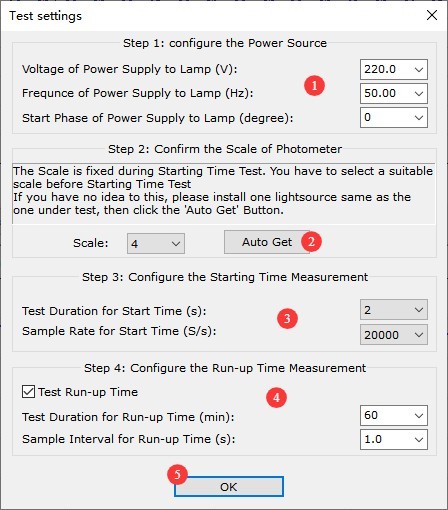
Figure 6-4
6.5 Viewing Test Reports
Refer to Section 4.3 and open the “Product Information” screen, as shown in Figure 6-5.
| Number | Note |
| ① | Enter reports, products, and test information |
| ② | Reports, Auto-Increment Function for Product IDs |
| ③ | Once you have filled in and configured all the settings, click “OK” to save and exit. |
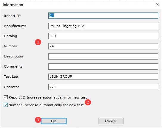
Figure 6-5
Then, following the instructions in Section 4.3, print the test report or export the test data.
7. Daily Maintenance and Care of Equipment
7.1 Routine Maintenance
7.1.1 Daily Cleaning
Be sure to turn off the power and unplug the power cord before cleaning. We recommend wiping the device with a soft, antistatic cotton cloth and a mild detergent; do not spray liquids directly onto the device. Do not use chemical solvents such as benzene, toluene, or acetone.
7.1.2 Routine Inspections
Before each use, check the power cord and terminal connections to ensure there are no loose connections or signs of burn damage; after turning on the unit, check that the indicator lights and display are functioning properly.
7.2 Maintenance Guidelines Specific to Photometric Probes
The probe is a precision optical device; do not bump, drop, or expose it to direct strong light. Never touch the probe’s light-sensitive surface with your bare hands; gently wipe away dust with lint-free lens paper. If the probe will not be used for an extended period, secure the probe cap, place it in a moisture-proof storage case, and store it in a dry, cool place.
7.3 Storage Specifications
7.3.1 Storage Environment Requirements
Temperature: 5°C to 35°C; humidity: ≤75% RH; dry, dust-free environment free of corrosive gases.
7.3.2 Long-Term Storage Operations
Turn off the power and unplug all cables; clean the equipment and wrap it in dust-proof film; turn on the power for 10 minutes each month to prevent moisture damage to the components.
7.4 Calibration Interval Requirements
To ensure the measurement accuracy and operational reliability of the equipment, it is recommended that it be sent periodically to a qualified third-party metrology laboratory for calibration. The recommended calibration interval is 12 months. Users may determine the specific calibration interval based on frequency of use, environmental conditions, and quality system requirements.
8. Troubleshooting and Resolving Common Problems
8.1 LSRF-3 Stroboscopic Start-Up Rise Tester
| Fault Symptoms | Possible Causes | Procedure |
| The device frequently restarts on its own, and the screen flickers | Insufficient or Unstable USB Power Supply | While connecting the USB cable, plug the power adapter into the device. |
| Software lags or closes unexpectedly | Insufficient computer permissions | Please log in to your computer using an administrator account and try again. |
| Inaccurate photometric test parameters | Not calibrated or calibration failed | Try again after calibrating according to Section 5.2 or 6.2. |
8.2 LSP Series Power Supplies
| Fault Symptoms | Possible Causes | Procedure |
| Unable to Power On | Input voltage selector switch malfunction, blown fuse | Check the input voltage selector switch; turn off the power, eliminate any output short circuits or overloads, replace the fuse with one of the same rating, and do not increase the current rating. |
| The fan isn’t spinning | Dust buildup, motor failure | Turn off the power and clean the dust from the fan; if the problem persists, please contact us for repair or to have the fan replaced. |
| Error code 02 in the lower-right corner of the display | In the event of an output short circuit, excessive current, or excessive power, the power supply will automatically cut off the output to protect itself. | Please turn off the LSP power supply, check the wiring, and resolve any output short circuits before restoring power; if the load current or power exceeds the power supply’s upper limit, you will need to purchase a larger AC power supply. |
| Error code 01 in the lower-right corner of the display | A fuse has blown | Please turn off the LSP power supply and unplug the power cord. Check all fuses on the rear panel of the power supply and replace them with fuses of the same rating. Do not increase the current rating. |