English
 中文简体
中文简体 English
 Русский
 Español
 Português
 Türkçe
 العربية
 Deutsch
 Polski
 Italiano
 Français
 한국어
한국어 ไทย
ไทย Tiếng Việt
 日本語
日本語





























Goniophotometer For Automotive And Traffic Signal Lamps
User's Manual
Applicable LISUN models: LSG-1950S
(Note: The images in the manual for the main unit The installation and commissioning procedures for the LSG-1890B and the LSG-1950S are identical.)
Please confirm that the darkroom has been built and finished in full accordance with the design drawings we sent you. If there are any discrepancies, please contact us.
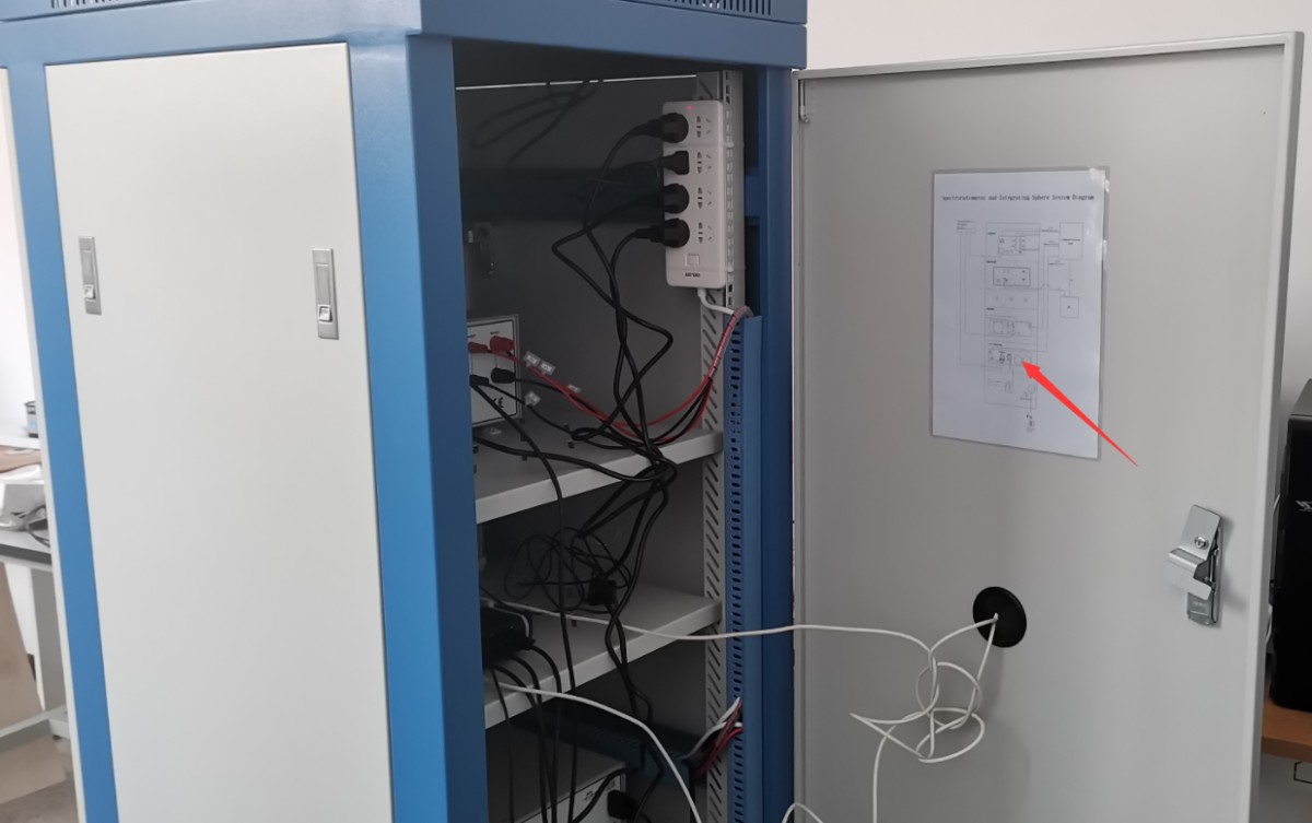
A wiring diagram is provided on the back of the cabinet. The necessary wiring, terminal blocks, and communication boxes have already been installed inside the cabinet. Following the wiring diagram, place the equipment to be installed in the cabinet into their respective positions. From top to bottom, the order is as follows: RT-200 angle controller, LS series electrical parameter meter, DC power supply, and AC power supply.
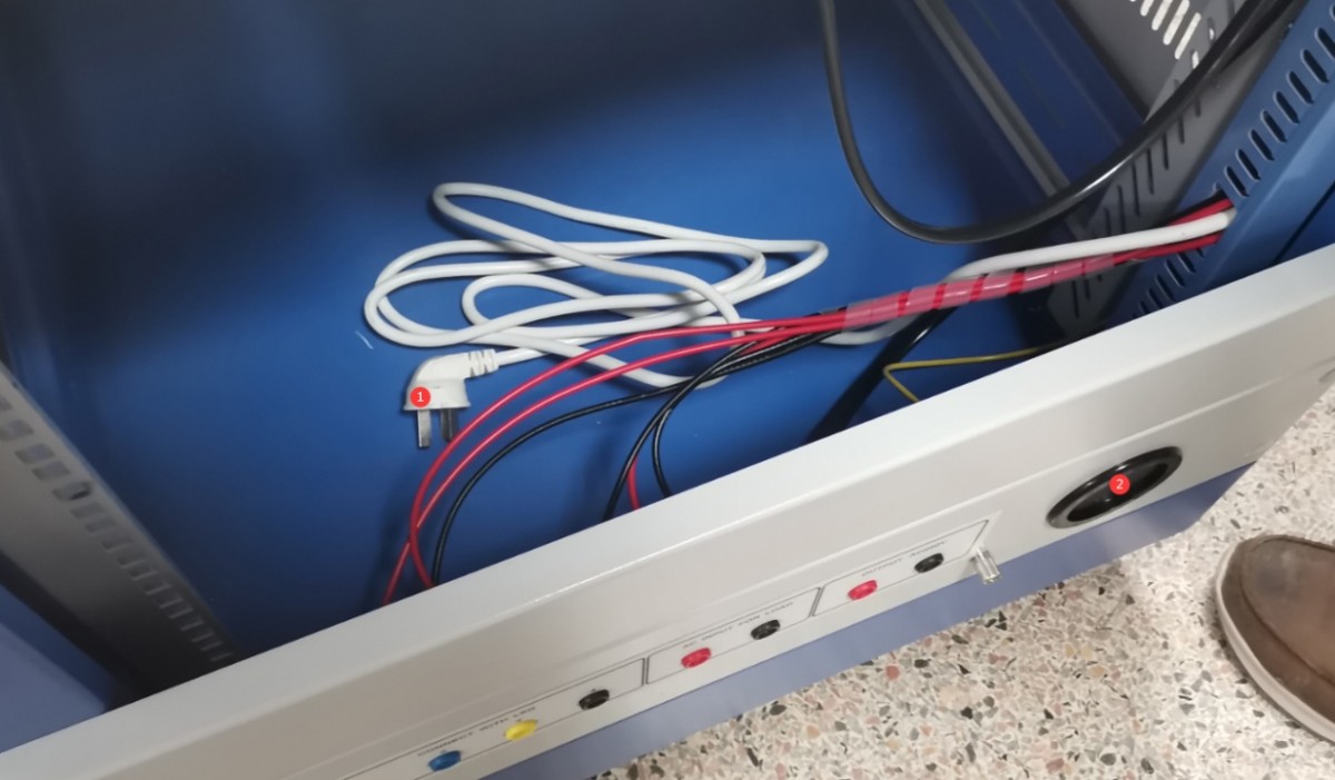
The bottom layer of the cabinet① contains the main power cord for the cabinet; feed it through the opening②.
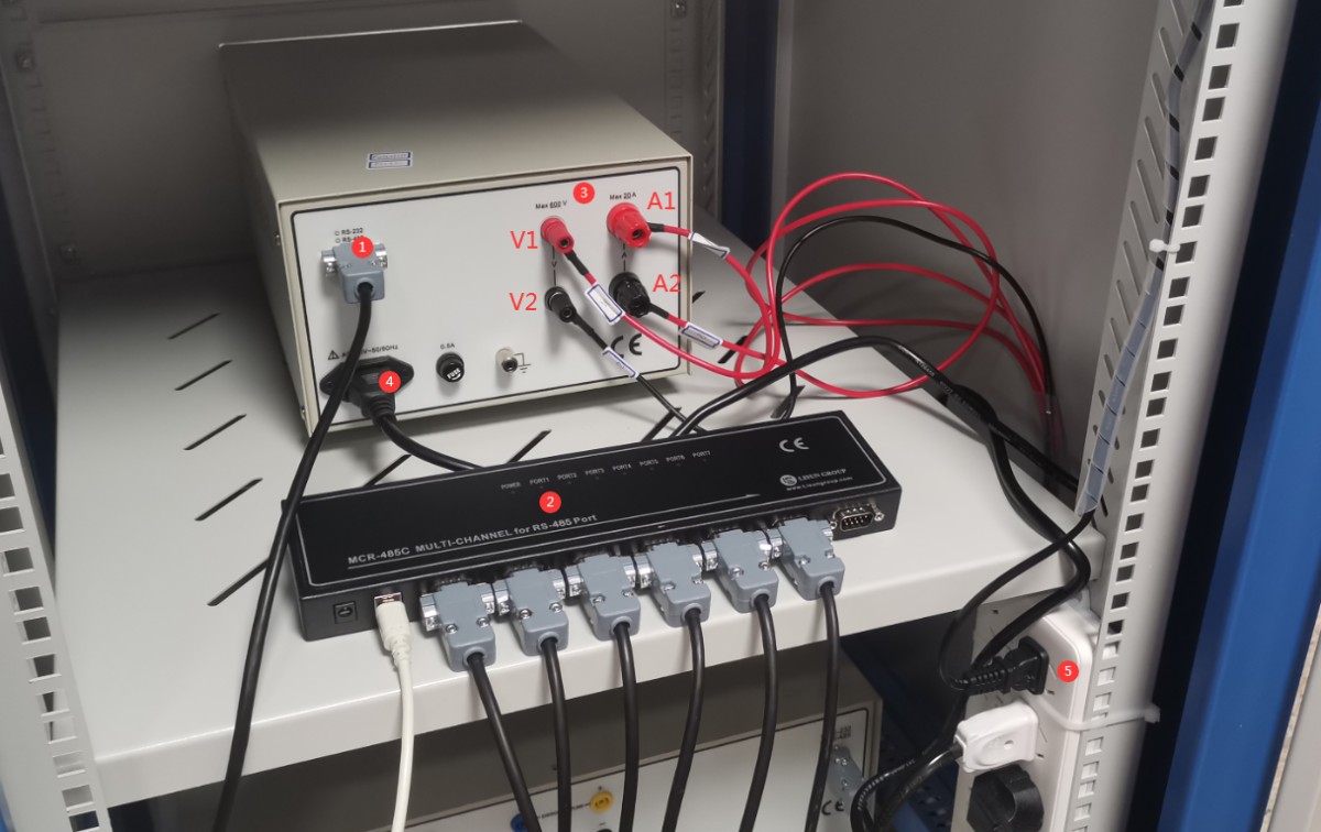
Wiring on the back of the electrical parameter meter. ① Communication cable; connect the other end to communication box ② inside the cabinet. ③ Four test leads for voltage and current; connect them to the correct terminals as indicated by the labels in the diagram. ④ Power cord; connect it to terminal block ⑤ inside the cabinet.
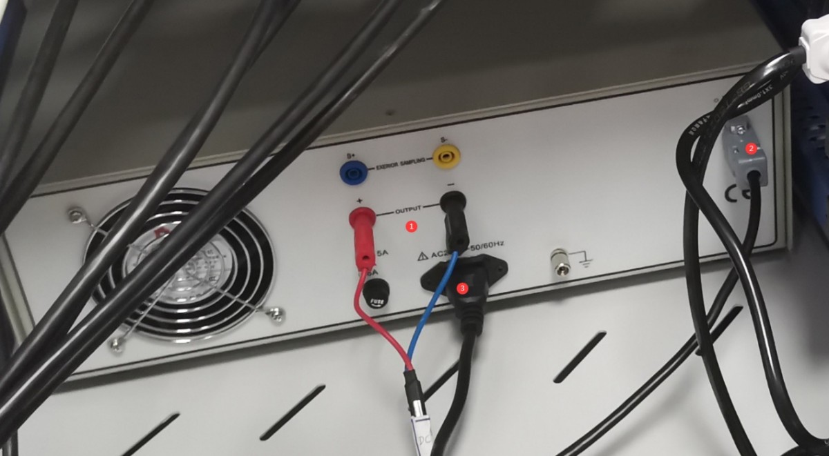
Wiring on the back of the DC power supply. ① Power output wires—pay attention to the positive and negative terminals. ② Communication cable—the other end connects to the communication box. ③ Power cord—connects to the terminal block inside the cabinet.
AC power output cable.
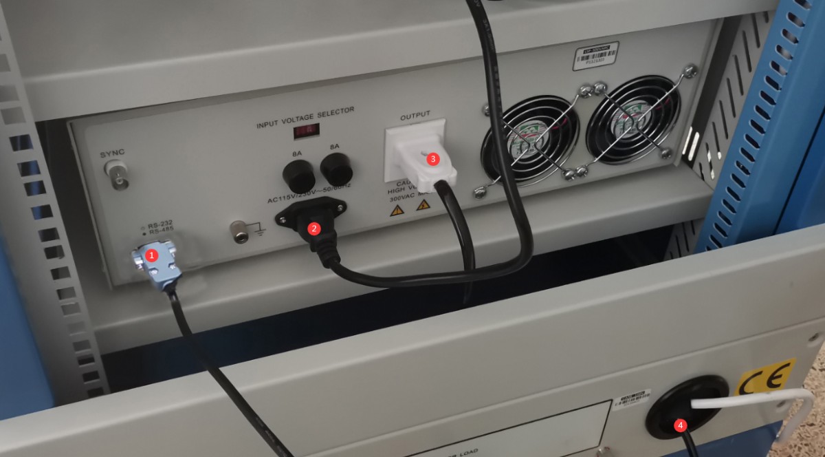
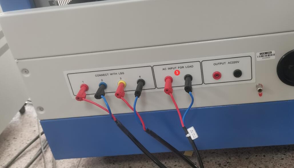
AC power rear connection cable. ① Communication cable; the other end connects to the communication box. ② Power cord; connects to the power strip. ③ Power output cable; passes through opening ④ and connects to the two terminals ⑤ at the bottom of the cabinet.
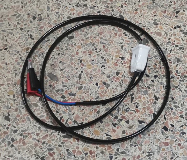
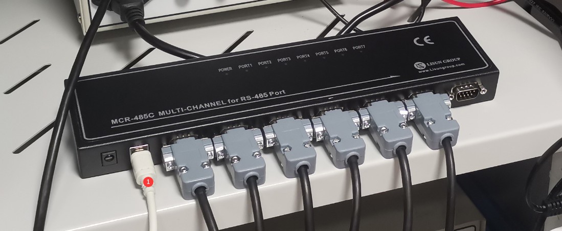
Connect the other end of the communication box USB cable ① to the computer.
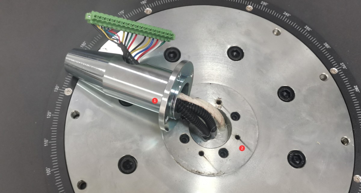
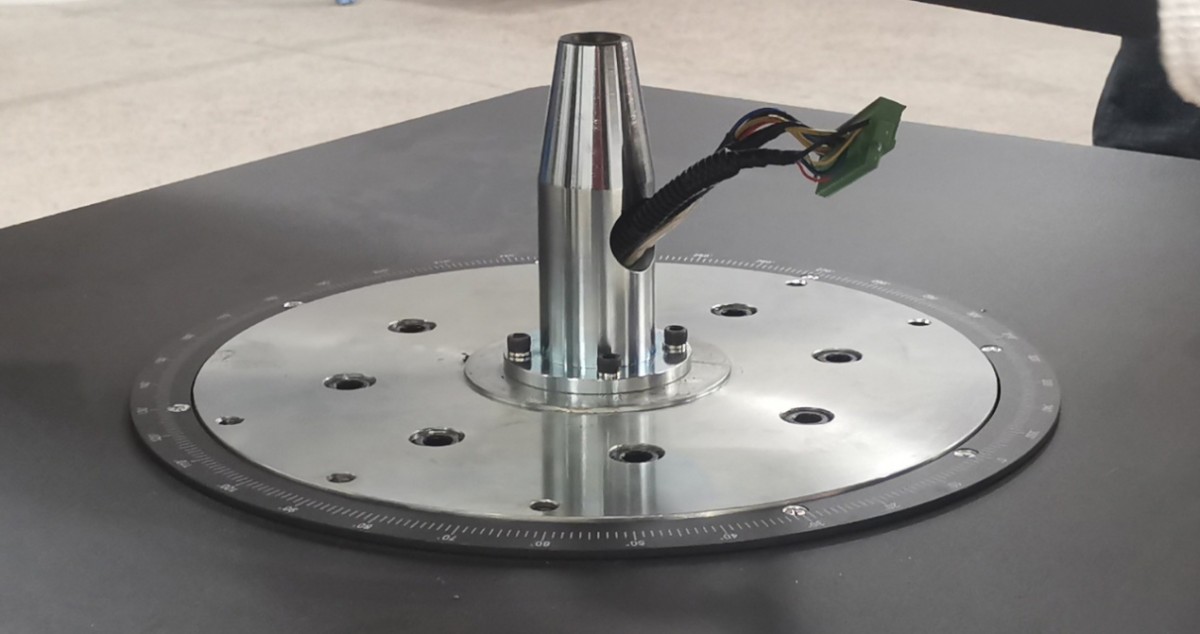
The same number is engraved on the main unitThe base tapered sleeve ① and the corresponding position on The ②. Rotate the tapered sleeve until the two numbers are aligned, then secure the tapered sleeve using the Allen screws provided by Shanghai Lishan.
Pull back the dust cover at turntable ①.
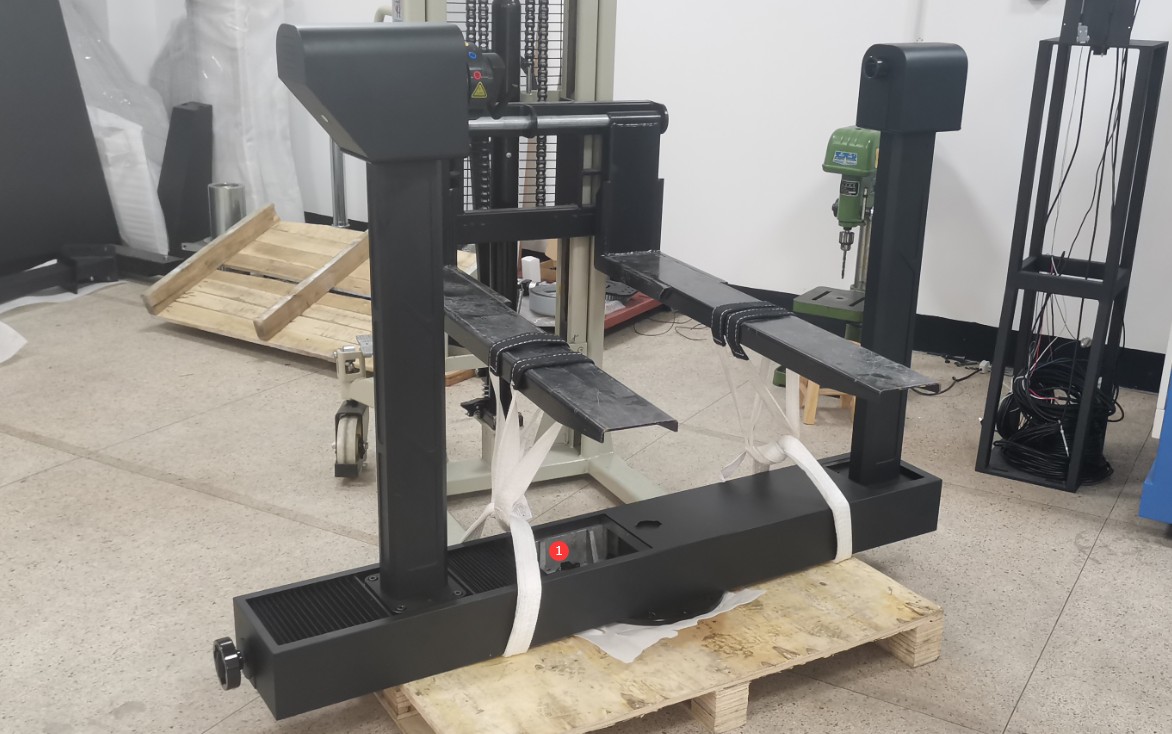
Use a forklift to lift the turntable. The orientation of turntable ① should align with that of the base terminal block. Gently lower the turntable onto the base.
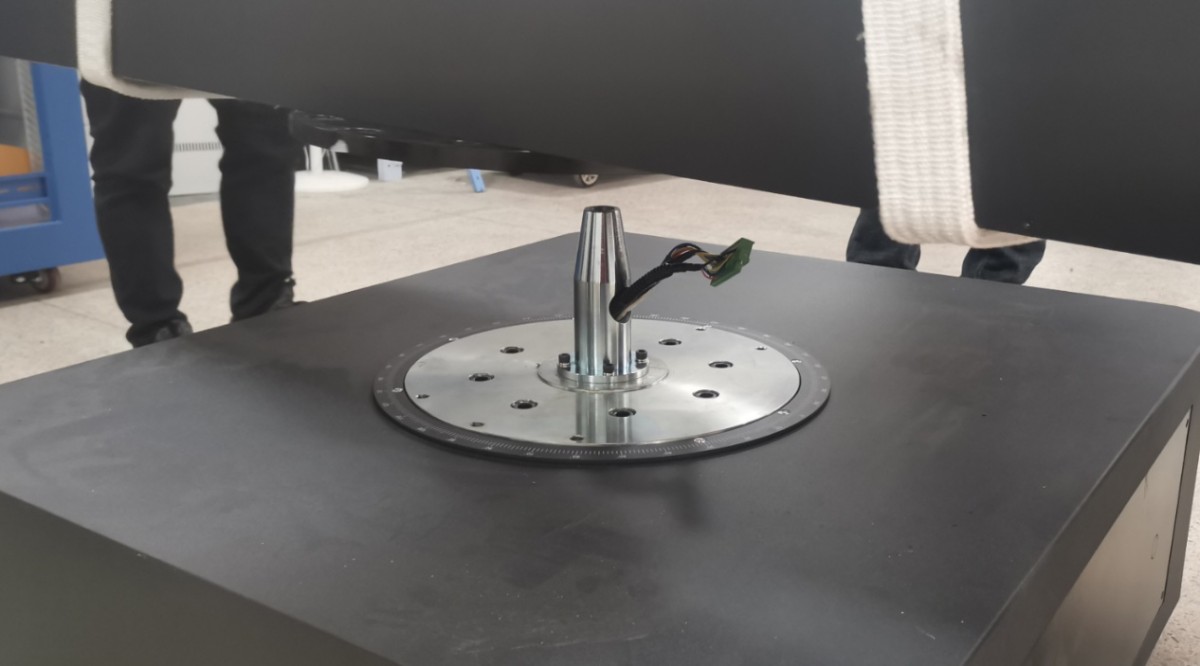
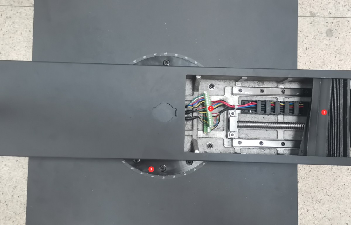
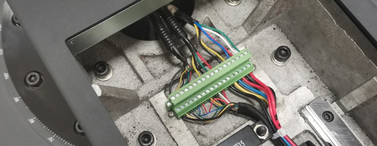
Fine-tune the orientation of the turntable so that the six screw holes ① on the turntable align with the six screw holes on the base. Use the hex screws and washers provided by Shanghai Lishan to secure the turntable to the base.② Plug the base’s terminal block into the corresponding terminal block socket on the turntable. Then reinstall the dust cover ③ in its original position.
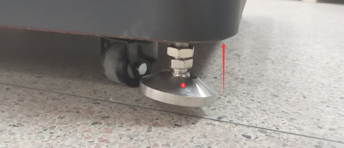
①Unscrew the four feet from the bottom of the main unit.
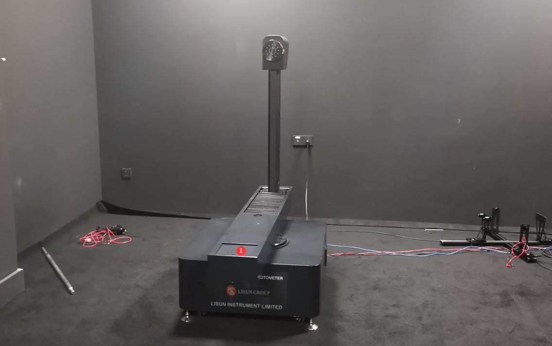
Position the Goniophotomoeter in the correct location according to the darkroom blueprints. Align the four sides of the base as closely as possible with the walls of the darkroom. Then① remove the auxiliary arm.
Assemble the probe and bracket, then position them in the corresponding locations as shown in the drawings.
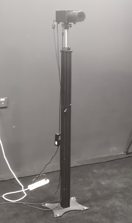
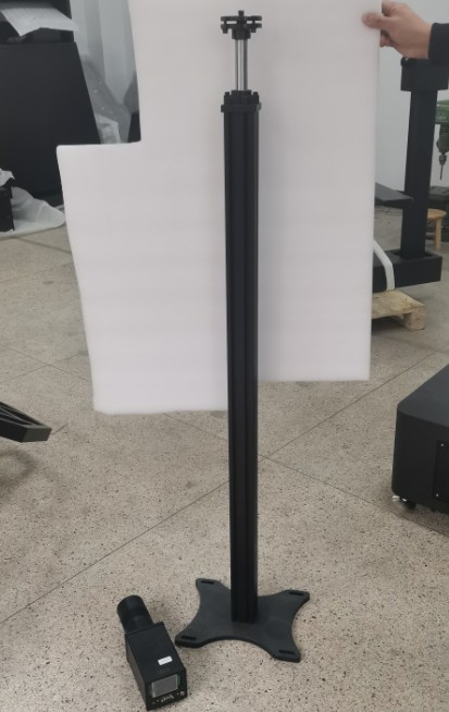
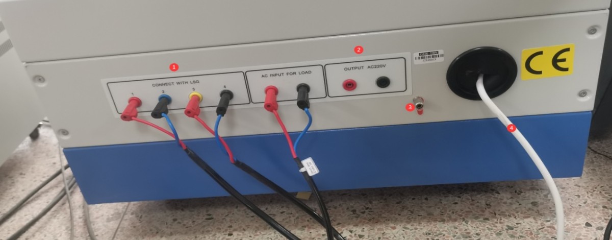
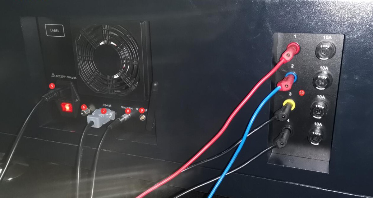
The four terminal blocks ①at the cabinet are connected to the Goniophotomoeter⑩; simply match them one-to-one by number.② The two terminal blocks are connected to the terminal block inside the cabinet and are used to supply power to all equipment in the darkroom, including the Goniophotomoeter, probes, and spectrometer. This allows you to conveniently control all equipment in the darkroom using the power switch on the cabinet.③ For the ground terminal, please use a wire to connect it to ground. Connect the ④cabinet’s power cord to a 220V, 50/60 Hz power source.
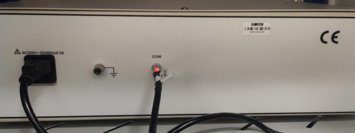
Connect the main unit of the Goniophotomoeter .⑤The power cord and ⑥ground terminal must be connected to ground using a wire. This ⑦is a “one-to-two” communication cable; the other end splits into two: one end connects to the communication box inside the cabinet via RS485, and the other end connects to the rear⑭ of the RT-200.⑧Connect the probe cables to the probe⑬. If only one probe is supplied, the default setting is near-field (N), so the far-field (F)⑨ connection is not required.
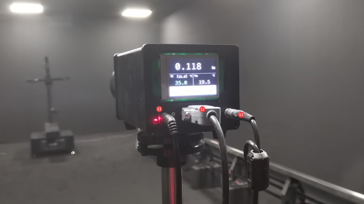
The probe has three wires that need to be connected:⑪ the power adapter,⑫ the communication cable (which connects to the cabinet’s communication box), and the trigger wire (⑬which connects to the main unit).
Hardware Debugging
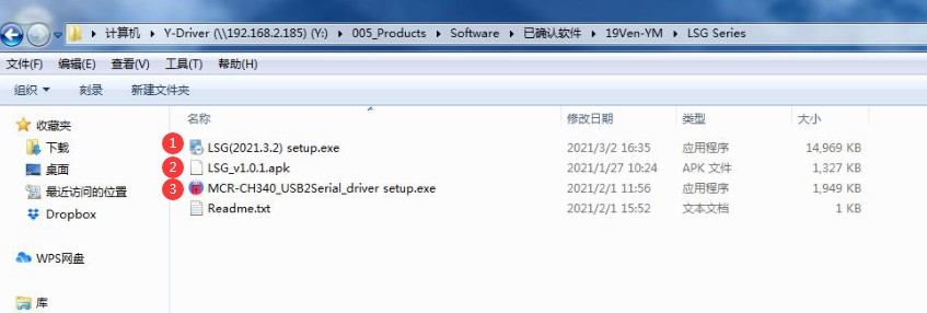
You will need to use software or an app for calibration. Copy all files from the CD to your computer. Double-click to install the Goniophotomoeter software ①and the communication box driver③.② The APK file can be copied to an Android phone for installation. The app can only be used to rotate the Goniophotomoeter; it cannot be used for testing. Since the software fully includes the app’s functions, the following instructions will use the software as an example.
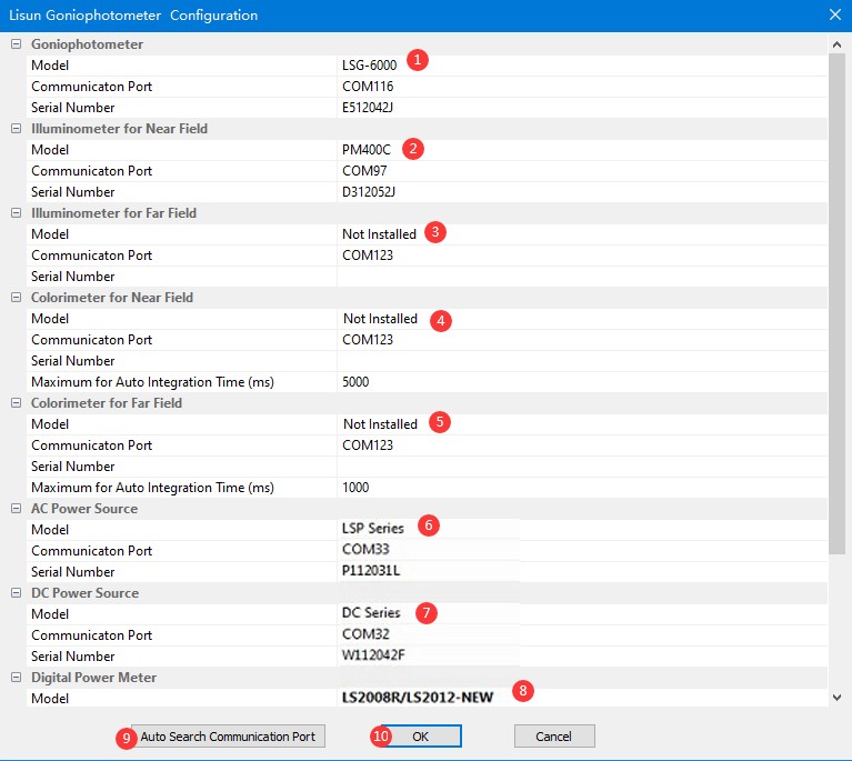
Connect the cabinet power cord. Turn on the power to the cabinet and all system equipment. Double-click to run the software. The first time you run the software, it will automatically open the system configuration interface. Select the correct① Goniophotomoeter, ②near-field photometer probe,⑥AC power supply,⑦DC power supply, and ⑧electrical parameter meter that you purchased. If your system does not include a ③far-field photometer probe or a spectrometer④⑤, select “Not Installed.” Once all selections are complete, click ⑨“Automatically Search for Communication Ports.”Once all communications are successful, click OK to save and exit. If communication fails for any individual device, check whether the correct model was selected and whether the corresponding communication cables are properly connected.
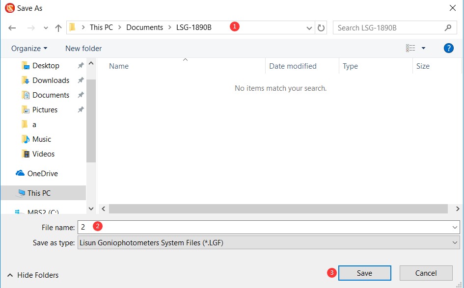
The software will then automatically proceed to the database save screen. Select the path① where you want to save the database, enter a file name②, and click Save③. Afterward, all test reports will be automatically saved in this database.
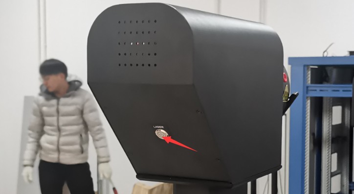
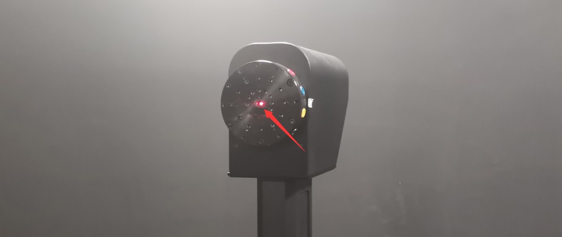
There is a laser switch on the back of the goniophotomoeter’s main arm. Turn on the line laser switch. You will then see a red line laser beam emitted directly in front of the main arm.
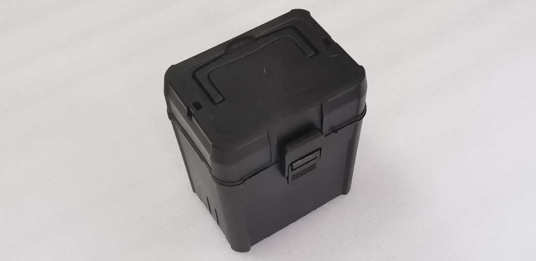
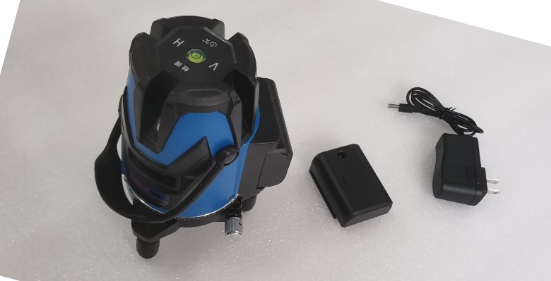
Remove the cross-line laser and the batteries. Insert the batteries into the cross-line laser. The “V” and “H” buttons on the top of the device are the touch switches for the vertical and horizontal lasers, respectively.
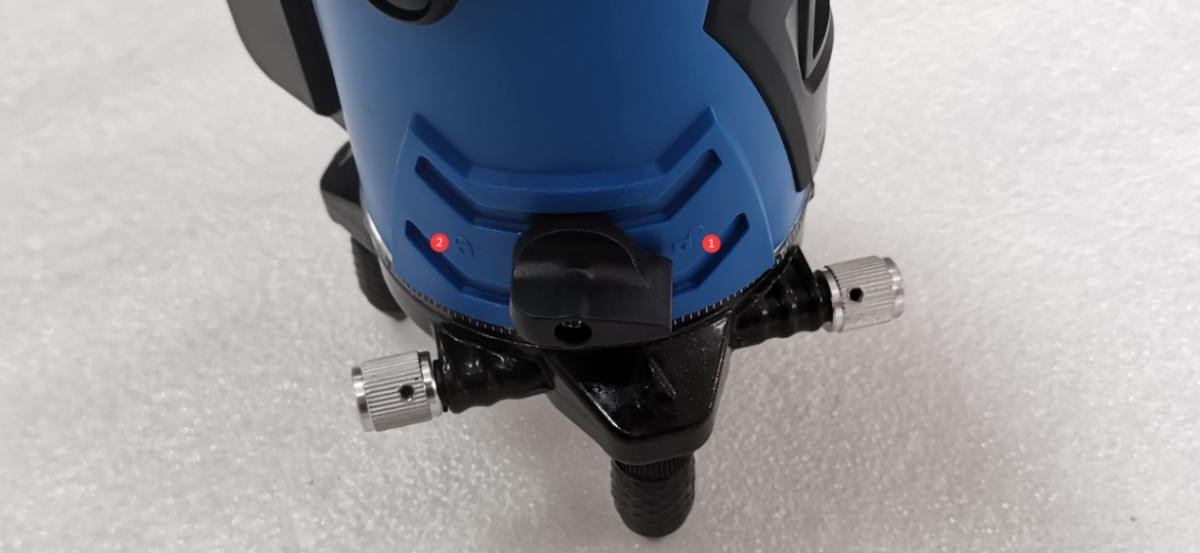
The power switch is located on the side of the device. When the switch is set to the unlocked position ①, the device turns on. When the switch is set to the locked position ②, the device turns off.
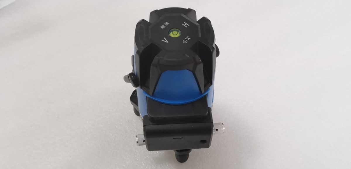
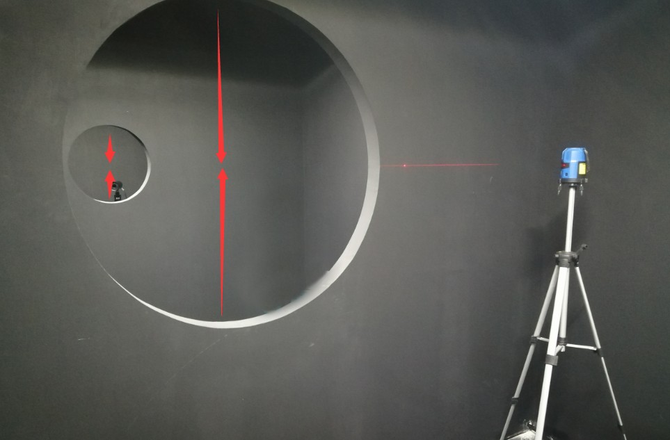
Turn on the cross-line laser and align it so that it passes through the exact center of all aperture rings. Note: Once the cross-line laser is turned on, the horizontal laser beam will automatically level itself. If the cross-line laser is positioned at too steep an angle, preventing the horizontal laser beam from automatically leveling, the cross-line laser will emit an audible alarm. The cross-line laser head can be rotated freely.
Open the software. Click ①“Position” to enter the angle control interface.
For the Horizontal angle, ①click the continuous rotation button in any direction. At this point, the Horizontal axis of the Goniophotomoeter will begin to rotate continuously. Please note: Avoid placing tools or other objects on the goniophotomoeter unit to prevent damage to the equipment during rotation.
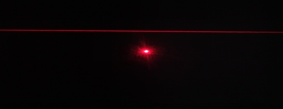
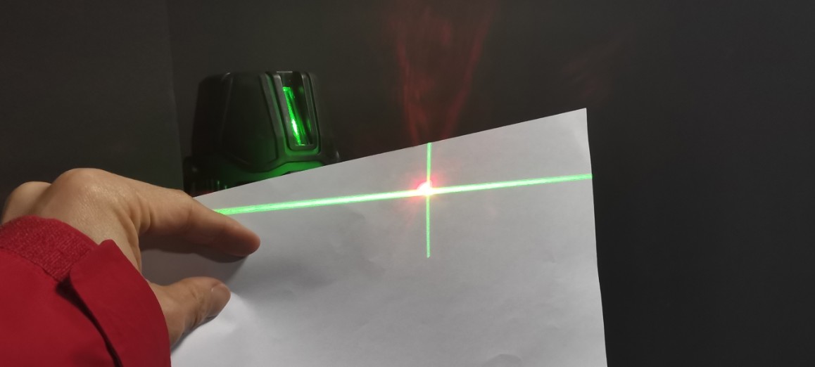
At this point, observe the horizontal laser beams emitted by the single-line laser and the crosshair laser from the goniophotomoeter’s main shaft.
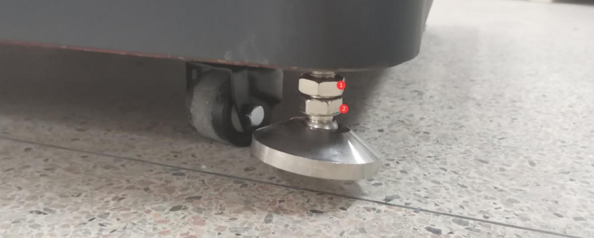
First, rotate all four leveling feet of the goniophotomoeter until they make contact with the floor. Then, adjust the height of the four leveling feet. Note: If you turn the screws clockwise①, the leveling feet will lock in place; therefore, loosen the screws① as much as possible first, then use them② to adjust the height of the leveling feet.
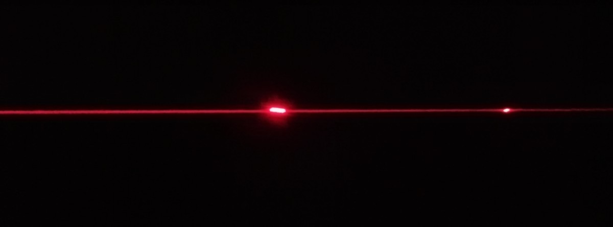
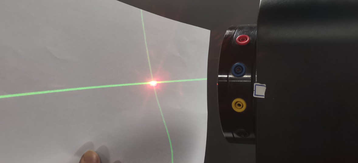
Adjust the height so that, regardless of the gamma angle of the Goniophotomoeter, the single-line laser always aligns with the horizontal laser, as shown in the figure below.
You will need sufficient patience to complete this step. Once adjusted, ensure that all four feet of the main unit are firmly on the ground. Then click “Stop” in the software to halt the rotation of the Goniophotomoeter. Next, lock all four feet in place. Once the main unit is securely positioned, do not move it, as doing so will cause discrepancies in the test results.
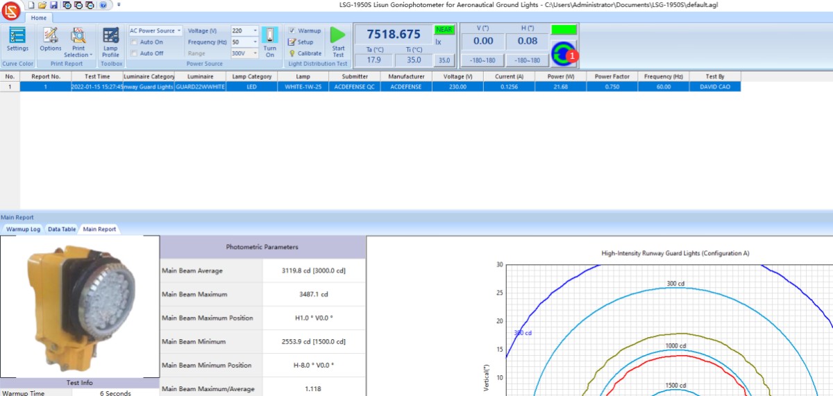
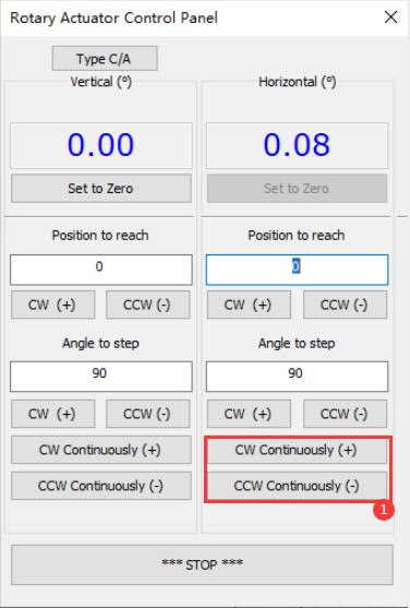
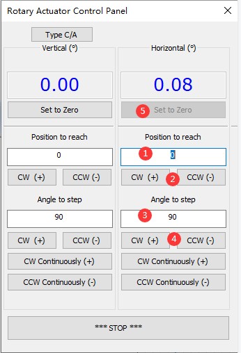
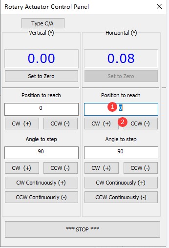
① Enter 0. ② Click any rotation direction. Rotate the Horizontal axis back to the 0-degree position.
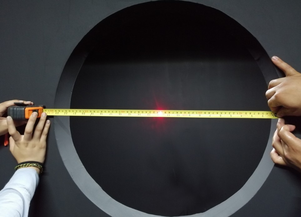
Check whether the single-line laser beam passes through the exact center of the horizontal plane of the last aperture. If not, enter a small angle value at ③ based on the actual situation—such as 0.1—then click ④ to rotate the Horizontal axis until the laser line is centered. Then click ⑤ to set the Horizontal axis to 0 degrees. The password is LISUNGROUP. Note: After setting the Horizontal axis to 0 degrees, do not arbitrarily reset it to 0, as this will cause deviations in the test results.
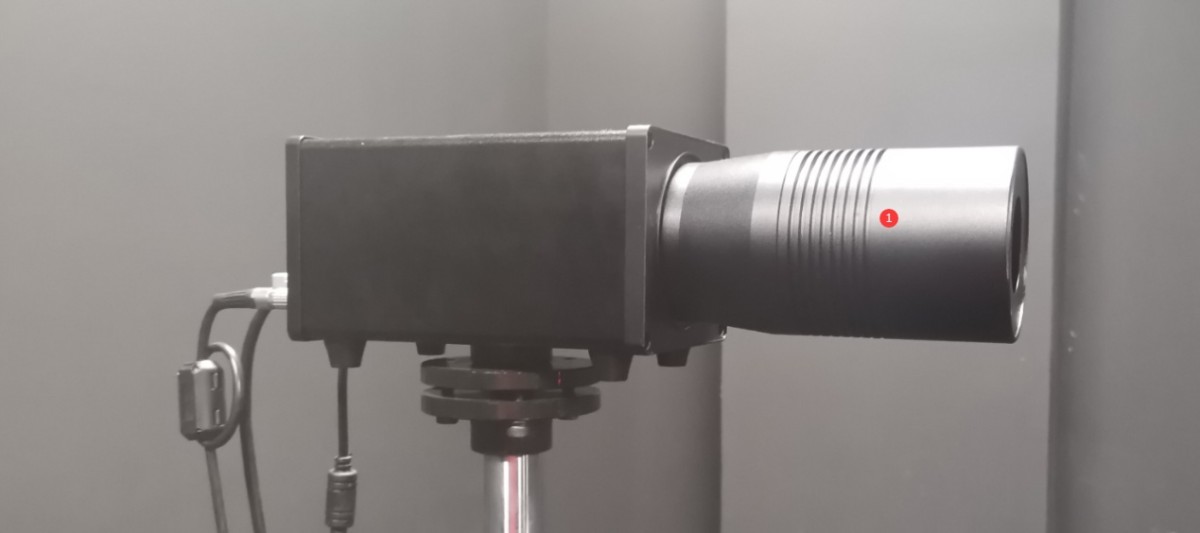
Remove the light shield ① from the photometer probe and install the reflector we provided.
The Gamma axis should still be at the 0-degree position. At this point, you’ll need to slightly move the probe base and adjust the screws at points ① and ② to set the probe’s height and orientation. Position the probe so that the straight laser beam coming from the main axis hits the exact center of the reflector and the reflected beam travels back along the same path.
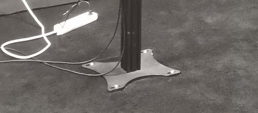
Then secure the probe base to the floor. Once secured, fine-tune the probe screws to ensure the orientation remains correct. Then remove the reflector and reinstall the light shield. Once the probe position is fixed, do not move it, as doing so will cause deviations in the test data.
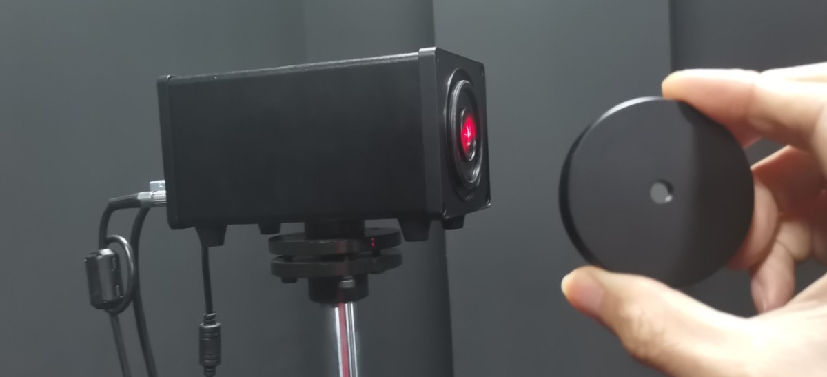
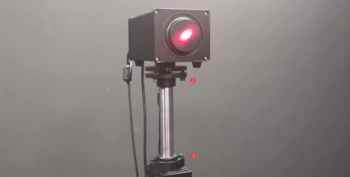
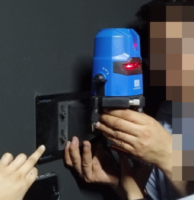
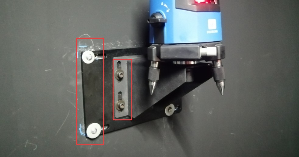
The cross-line laser must be mounted on a side wall. ① Enter 90 or 270 degrees (depending on the actual conditions shown in the drawings), ② click “Rotate.” Align the main arm’s straight-line laser directly with the wall where the cross-line laser is to be installed.
Mount the cross-line laser onto the tripod. Then place it against the wall.
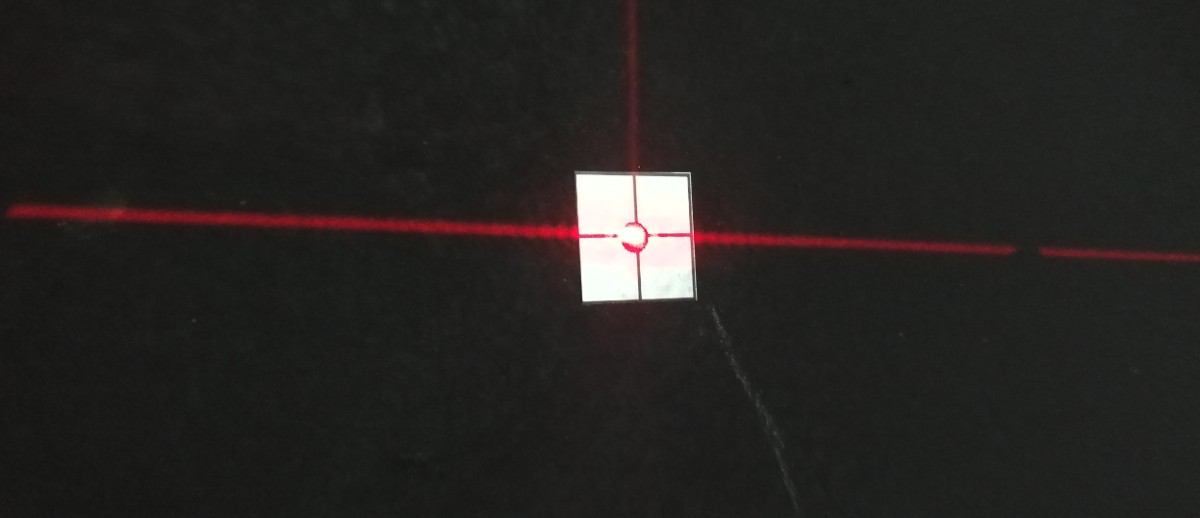
Turn on the cross-line laser. By moving the tripod and rotating the crosshair laser, align the center of the crosshair laser so that it perfectly coincides with the straight laser. Then secure the crosshair laser tripod to the wall. Once
secured, if necessary, you can still make fine adjustments to the screws on the tripod to ensure the crosshair laser remains in the correct position.
Then rotate the Gamma axis back to the 0-degree position. The cross laser is projected onto the opposite wall. You may make a permanent mark.
Installation and calibration are now complete. Turn off all equipment. Then clean the darkroom thoroughly. To prevent dust from entering the equipment, cover it with a dust-proof cloth. When using the equipment again, keep the darkroom as dust-free as possible.
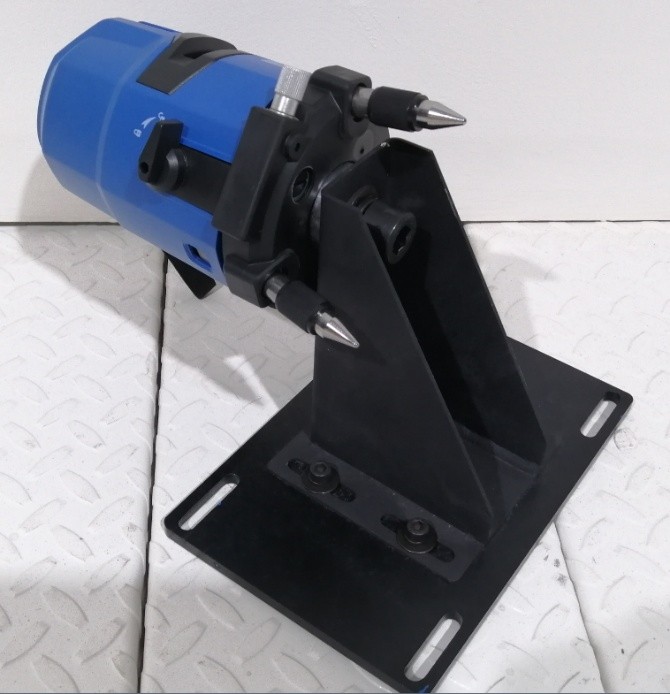
System Calibration
Before conducting formal testing, the system must be calibrated using a standard light source. Theoretically, if the darkroom remains unchanged during future use, recalibration will not be necessary.
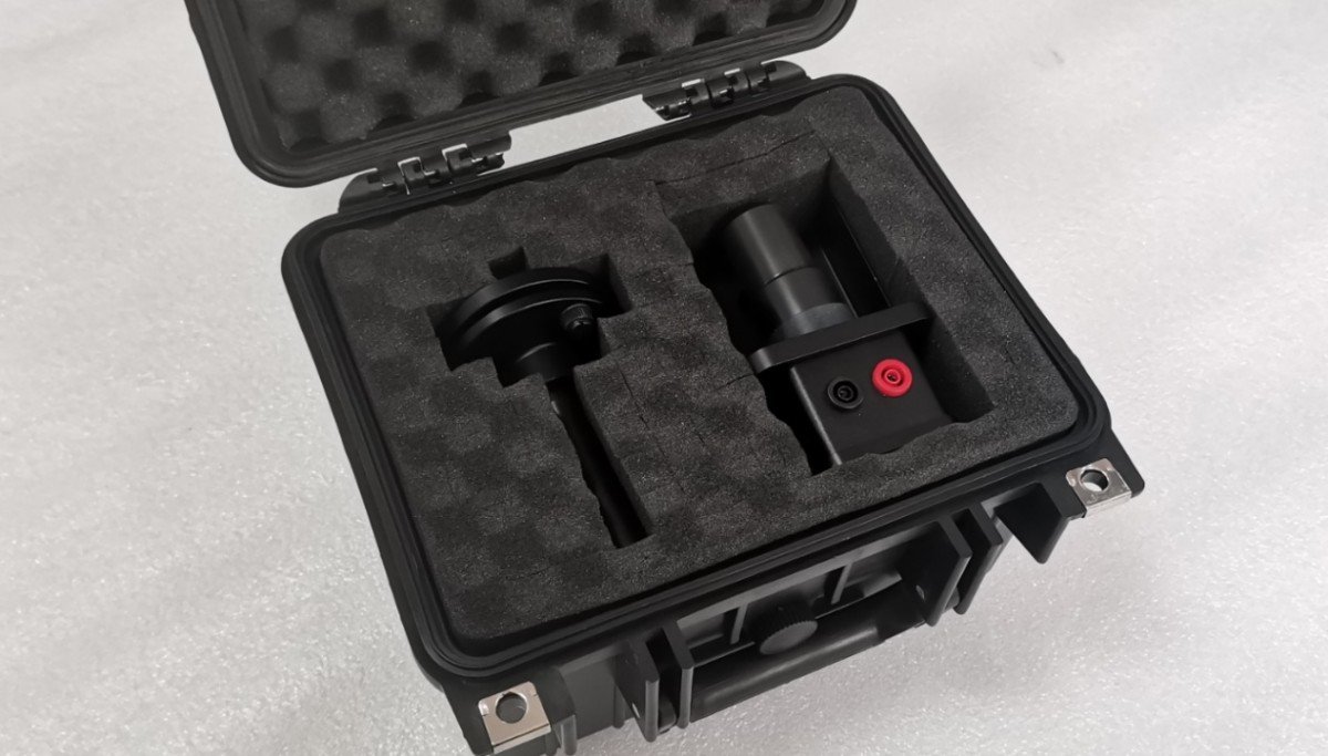
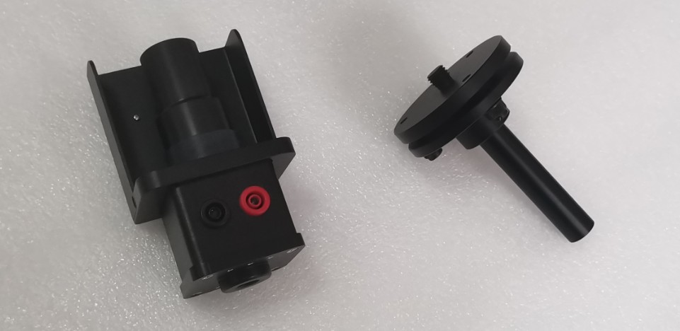
Open the standard lamp packaging box. Assemble the standard lamp bracket as shown in the figure below.
Install the reflector onto the standard lamp bracket.
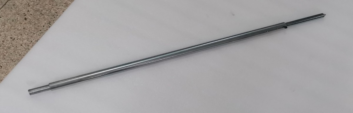
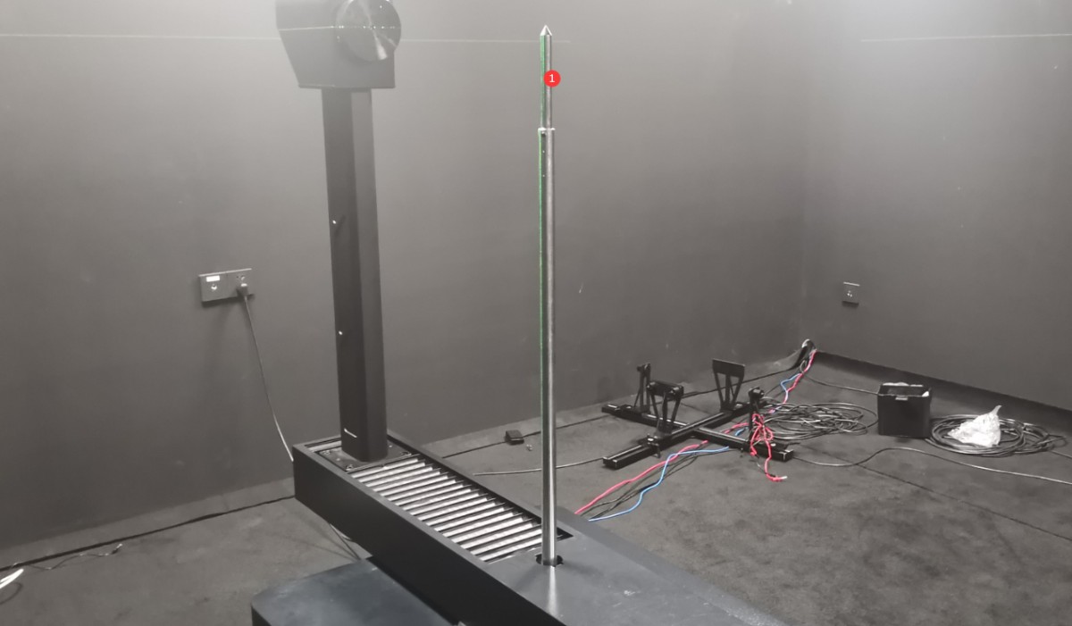
At this point, ensure that the “Horizontal” angle of the Goniophotomoeter remains aligned with the 0-degree position of the near-field photometer probe. Turn on the crosshair laser and verify that it is pointing in the correct direction. This is the reference rod.
Remove the top section① of the reference rod and mount the standard lamp bracket there.
Short-circuit the red and yellow terminals ①on the main shaft, and short-circuit the black and blue terminals. Connect the red and blue terminals to the standard lamp. The standard lamp bulb has a protective cover; remove the protective cover.
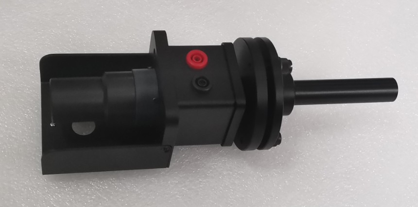
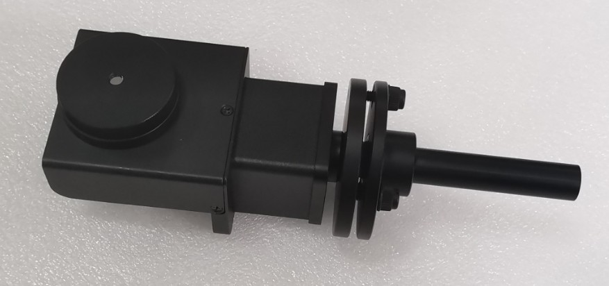
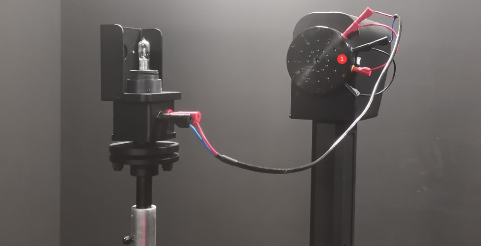
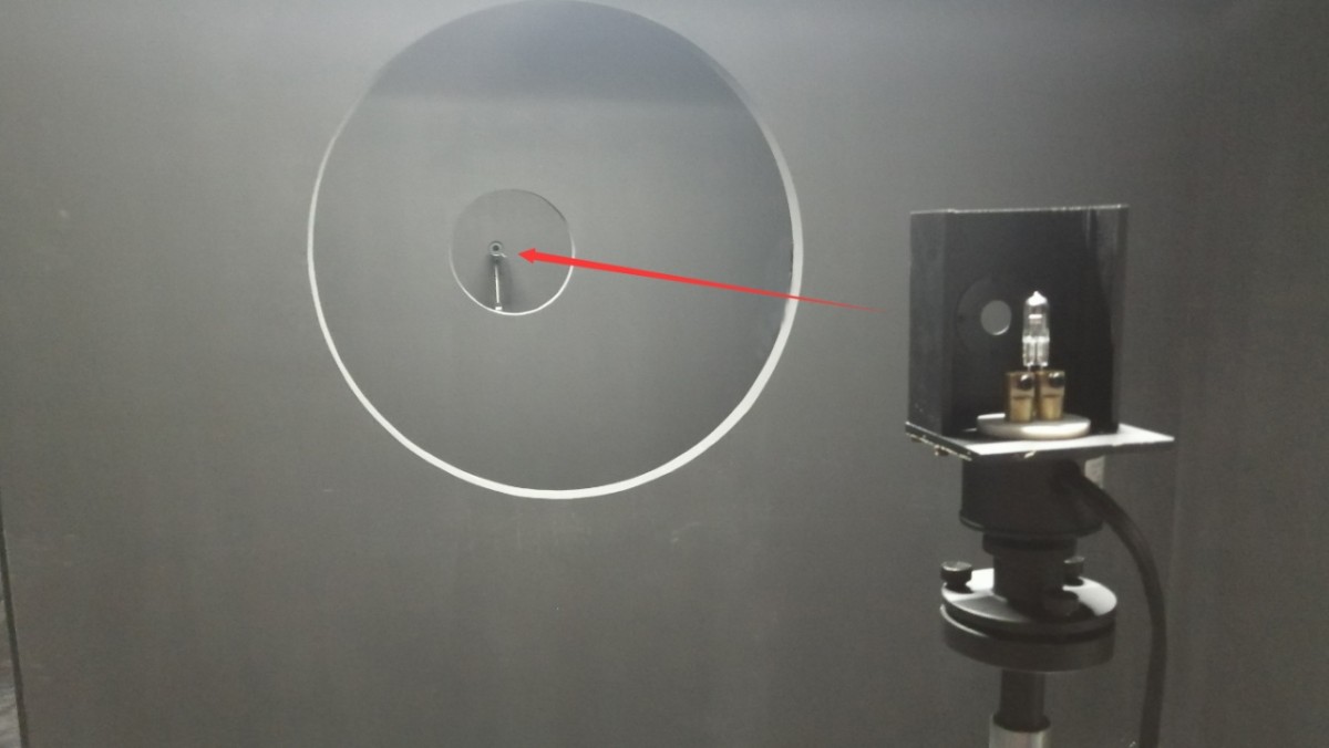
Now, adjust the three screws at location ① and the position of the standard lamp so that the cross-shaped laser beam is directed at the exact center of the reflector, and the reflected horizontal and vertical laser beams align with the horizontal and vertical beams of the cross-shaped laser.
Once adjusted, turn off the cross-shaped laser. Then remove the reflector.
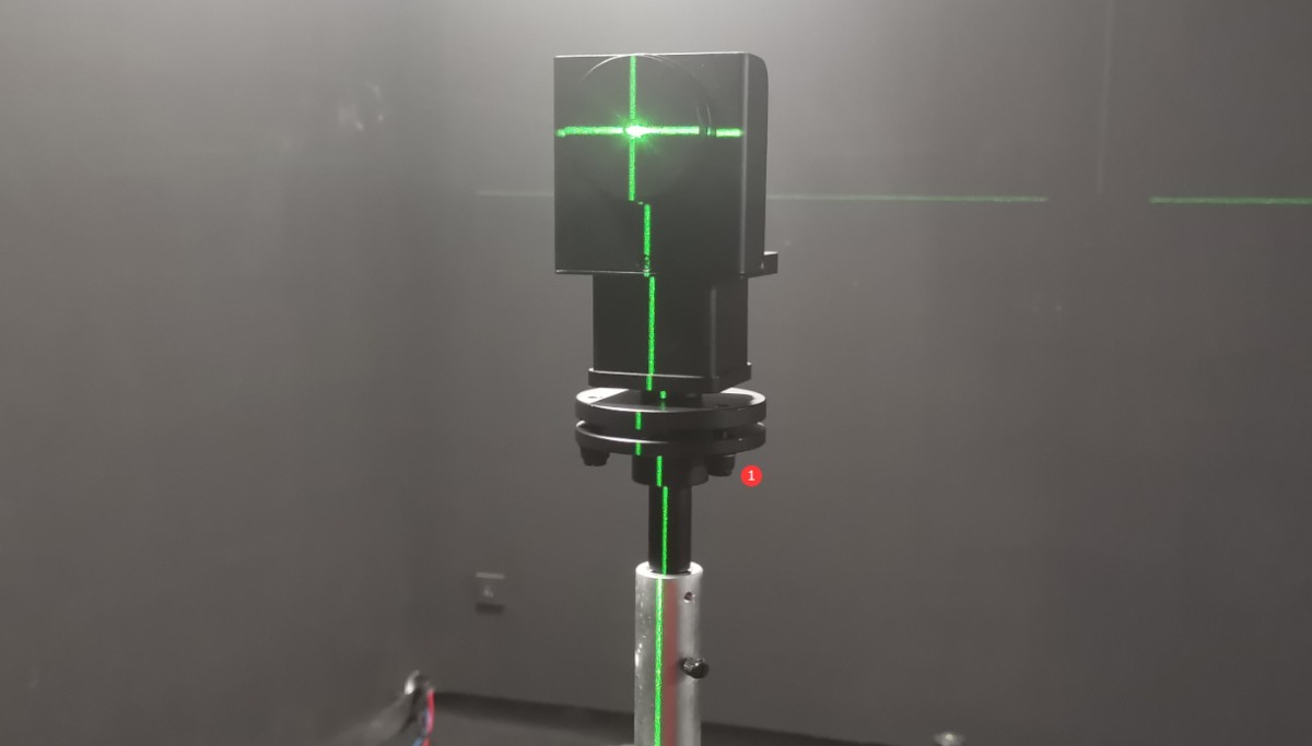
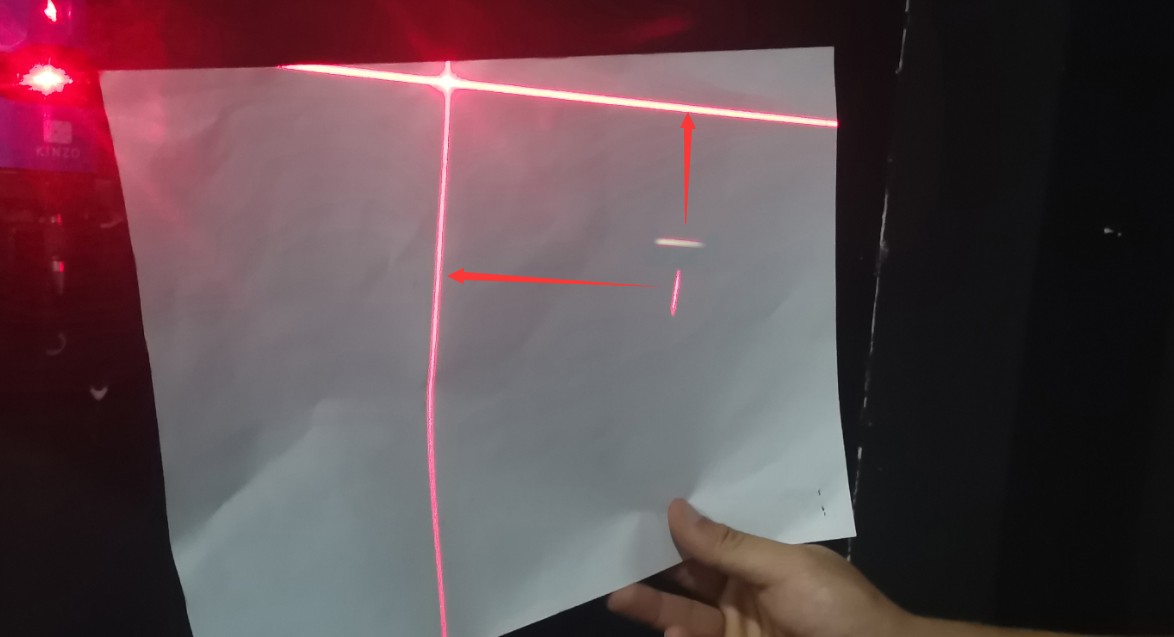
All Standard Light Sources are constant-current DC light sources. Set the AC/DC switch on the cabinet to DC.
Open the software angle controller, then rotate the Horizontal angle clockwise or counterclockwise by 90 degrees as needed—that is, to the 90-degree or 270-degree position—so that the circular hole in the Standard Light Source bracket is directly aligned with the photometric probe.
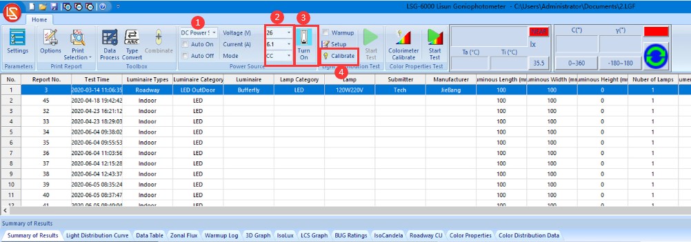
①Select the DC power supply.② Since the Standard Light Source is a constant-current light source, select CC (Constant Current mode). Enter the reference voltage and calibration current according to the Standard Light Source certificate, then ③click to turn on the Standard Light Source. Turn off all other light sources in the darkroom. The Standard Light Source requires 15 minutes to reach a stable state. Then click④ to enter the luminous intensity calibration interface.
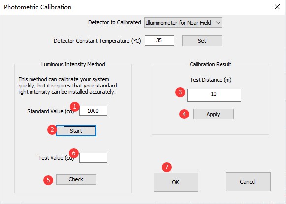
①Enter the correct luminous intensity value based on the standard lamp certificate. ②Click “Start.” After ③calibration is successful, the software will automatically calculate the test distance.④Click “Apply.” If you wish to double-check the real-time luminous intensity data, click “Test⑤.” ⑥Under normal circumstances, the real-time luminous intensity displayed should be very close to the entered value. Then click⑦ “Save and Exit.” After
calibration is complete, you can turn off the standard lamp via the software. Once the standard lamp has cooled, place it back in its packaging and store it properly.
Test
According to the standard, automotive lights and signal lights must undergo A-Alpha testing.
Floodlights must undergo B-Beta testing. All
other lighting fixtures, such as streetlights, downlights, panel lights, and so on, are tested using C-Gamma.
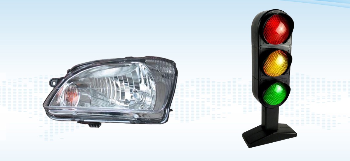
The LSG-1950S goniophotomoeter software is specifically designed to perform A-Alpha tests on automotive headlights and signal lights in accordance with standards. (If you need to perform other tests, additional software and accessories are required; please contact us.)
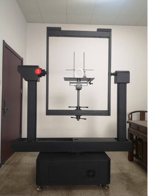
Install the fixture and sample as shown in the figure. Use the cross-laser on the wall to ensure the sample is positioned exactly in the center. ① Connect the sample’s power cord to The.
Note: When the horizontal angle is rotated to the 90-degree position, the light-emitting surface of the sample should be facing directly toward the probe. After the
sample is installed, close the darkroom door and turn off all other lighting in the darkroom.
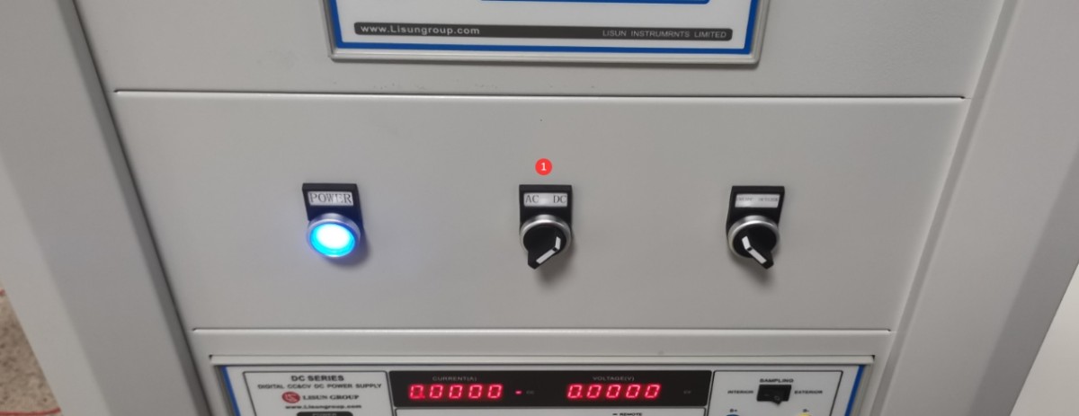
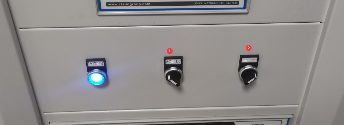
Depending on the lamp being tested, switch the AC/DC switch ① on the front of the cabinet to the correct position. ② is the internal/external sampling switch for electrical parameters; always set it to “OUTSIDE” (external sampling).
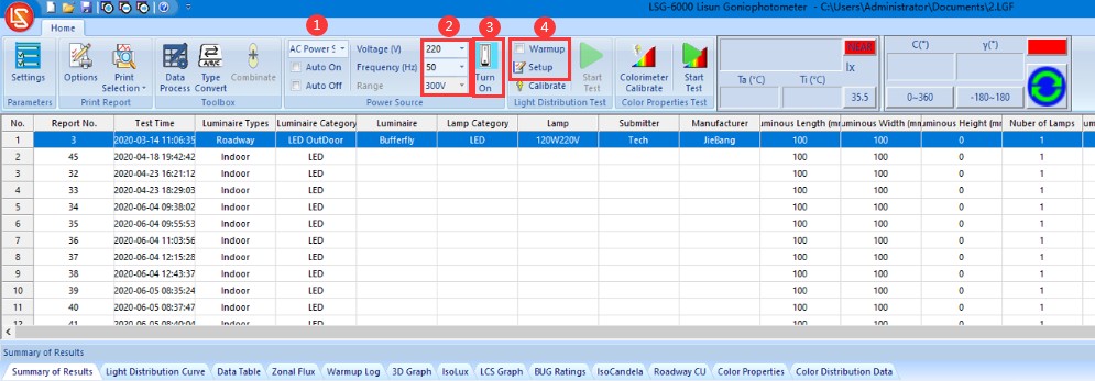
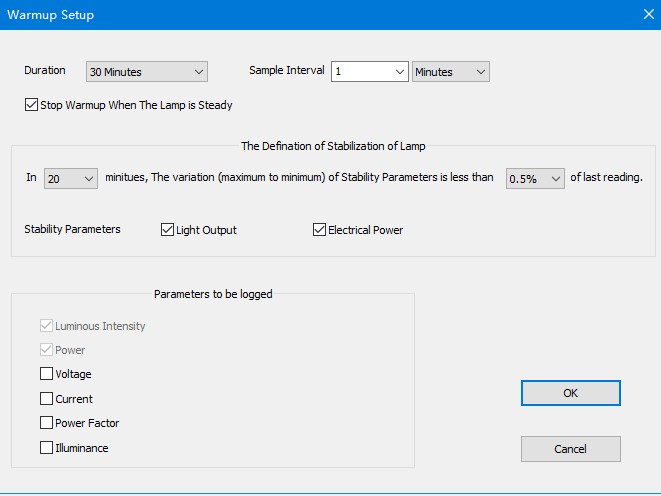
In the software: ① Select the correct power supply; ② Enter the appropriate electrical parameters; ③ Turn on the lamp under test. Click ④ “Settings” to configure the warm-up parameters. Once
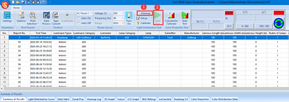
configured, if warm-up is required, check the warm-up option at ①. Click ② to enter the test parameter settings screen.
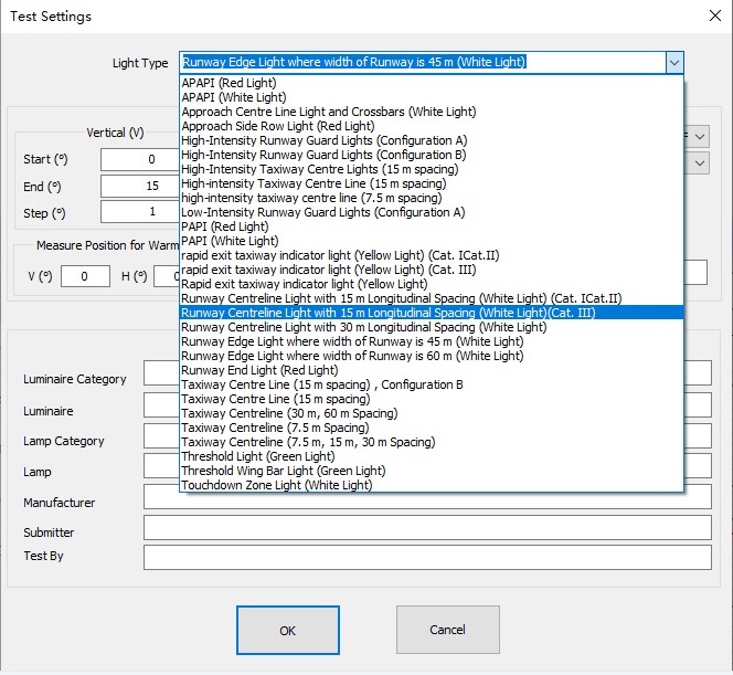
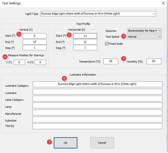
Select the type of light fixture you want to test.
① V-angle test range and interval angle. ② H-angle test range and interval angle. ③ Select “Normal Speed” for the test speed. ④ Select the monitoring angle during the warm-up phase; the (0, 0) position is generally sufficient. ⑤ Enter the temperature and humidity of the test environment. ⑥ Enter the sample information. ⑦ Click “OK” to start the test.
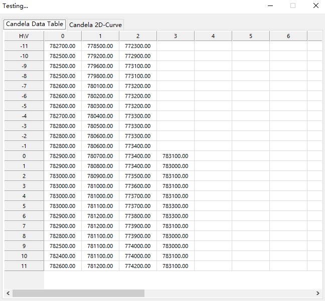
Then just wait for the test to finish.
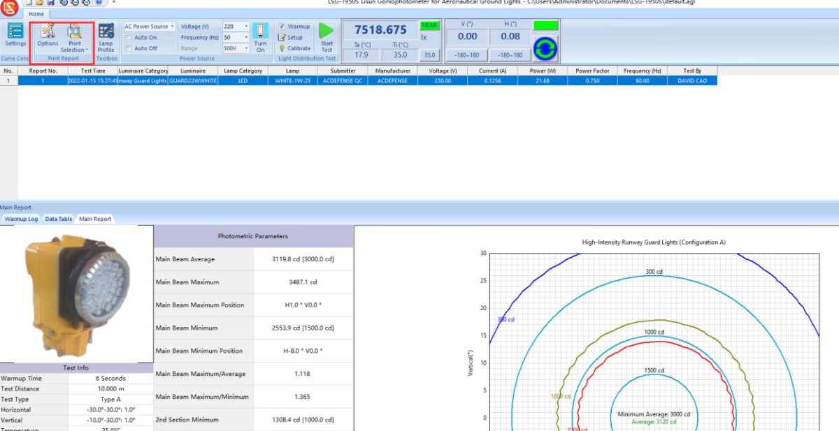
Confirm the print options and print the test report.
LED Luminaires and LED Power Driver Test Solution
Goniophotometer System: LSG-5000, LSG-1800B, or LSG-1700B
Spectroradiometer & Integrating Sphere Test System: LPCE-2 or LPCE-3
LED Life Maintains a Test System in Accordance with LM-80: LEDLM-80PL
Waterproof Test for IPX5 and IPX6 Levels: JL-56
Dustproof Testing Machine for IP5X and IP6X Testing: SC-015
LED Power Driver Testers: WT2080 (for the lab) and ATE-2 (for the production line)
Electrical Safety Tester: LS9955
CFL and Electronic Ballast Test Solution
Goniophotometer System: LSG-1800B or LSG-1700B
Integrating Sphere and Spectrophotometer Test System: LPCE-2 or LPCE-3
Adjustable Reference Ballast: DYJ-50HZ, HCS-105A, and DYJ-HID
Electric Ballast Tester: WT5000 (for the lab) and ATE-1 (for the production line)
Digital Torsion Meter and Multiway Life Tester: CH338 and CH316
Electrical Safety Tester: LS9922I, ZRS-3H, ZY-3
EMC and EMI Test Solutions for CFL and LED Luminaires
EMI Test System: EMI-9KB or EMI-9KA
Electrostatic Discharge Simulator: ESD61000-2
EFT Immunity Measurement: EFT61000-4
Surge Generator: SG61000-5
Voltage Dips and Interruptions Generator: CSS61000-11
Ring Wave Generator: RWG61000-12