
 English
 中文简体
中文简体 English
 Русский
 Español
 Português
 Türkçe
 العربية
 Deutsch
 Polski
 Italiano
 Français
 한국어
한국어 ไทย
ไทย Tiếng Việt
 日本語
日本語





























Test Apparatus for Cable Tie Impact Test
User's Manual
Applicable LISUN models: LS-SU4068A、LS-SU4070-0.25KG、LS-SU4070-0.5KG、LS-SU4070-1.7KG、LS-SU4071A
1. Basic Understanding of Equipment
1.1 Scope of Equipment Application
1.1.1 Core Uses
The LS-CU Cable Tie Impact Test System is used to verify the impact resistance of plastic cable ties and to evaluate their structural integrity after being subjected to a free-fall hammer impact of a specified energy at room temperature and at the stated minimum operating temperature. It serves as the core testing equipment for cable tie type testing, factory random inspections, and quality verification.
1.1.2 Scope of Applicable Samples
This equipment is compatible with all types of self-locking and releasable plastic cable ties, covering a full range of tie samples with minimum declared loop tensile strengths ranging from ≤80 N to >1300 N. It can be used with test mandrels of various diameters to accommodate testing requirements for cable ties of different widths and lengths.
1.2 Applicable Standards
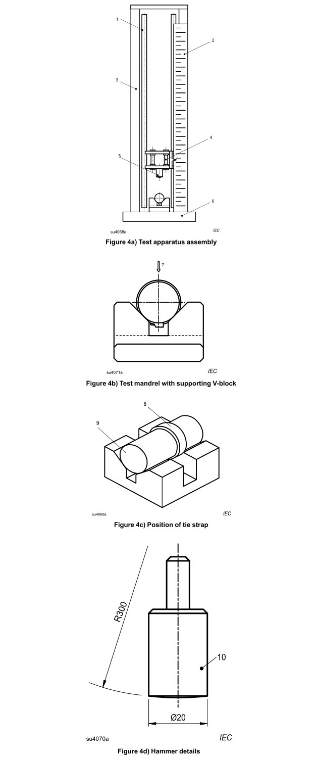
Designed and manufactured in strict accordance with Figures 4a through 4d in Section 9.4 of UL 62275, “STANDARD FOR SAFETY Cable Management Systems – Cable Ties for Electrical Installations.”
The impact energy parameters conform to the values specified in Table 7.
1.3 Test Principle
1.3.1 Principle of Free-Fall Hammer Impact
The equipment uses a free-fall impact method: a hammer of a specified mass is released to fall vertically, striking the body of the cable tie with a specified impact energy. The tie’s impact resistance is determined by observing the extent of damage to the tie after the impact.
1.3.2 Logic of the Low-Temperature Impact Test
For the minimum operating temperature validation scenario, first place the test mandrel with the sample installed in a low-temperature chamber to undergo low-temperature conditioning for the specified duration. After removal, quickly complete the positioning and impact operations within the time limit specified by the standard to simulate the cable tie’s impact resistance in extreme low-temperature environments.
Low-temperature testing can be performed using LISUN’s GDJW series of programmable High and Low Temperature Chambers.
1.4 Downloading Electronic Documents
We have already sent you the download links for the digital user manual, calibration certificate, warranty card, and other documents via email at the time of shipment. Please download them as soon as possible. If you have not received the email, please contact us to request the links again.
2. Safety Precautions
2.1 Operating Environment Requirements
The equipment must be placed on a level, sturdy concrete surface or test bench, with at least 50 cm of clearance around it for operation. Keep it out of direct sunlight and away from strong drafts.
The temperature range for storing and operating the equipment is 0°C to 40°C, with a relative humidity of ≤85%.
2.2 Operational Safety Guidelines
Safety goggles must be worn at all times during operation to prevent injury from flying plastic debris during the impact process.
When conducting low-temperature tests, you must wear freeze-resistant gloves when handling low-temperature samples and test mandrels to prevent frostbite.
While the equipment is in operation, do not extend your hands or head into the area directly below the impact hammer, and do not place any unrelated objects there. Do not stand close to the impact side.
It is strictly prohibited to add additional counterweights to the heavy hammer or modify the drop height without authorization; non-standard testing may damage the equipment or pose a safety hazard to personnel.
3. Equipment Overview
3.1 Standard Diagram
See Figure 3-1.
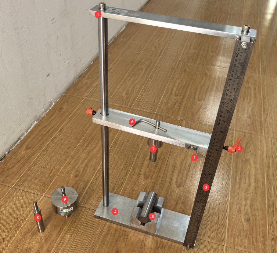
3.2 Product Photos
See Figure 3-2.
| Number | Note |
|---|---|
| ① | Equipment Racks and Guide Rails |
| ② | Rigid Base |
| ③ | Height Scale |
| ④ | Pointer |
| ⑤ | Sturdy screws to adjust the height of the impact hammer |
| ⑥ | Pins; the impact hammer is released when the pins are removed. |
| ⑦⑧⑨ | Impact Hammers of Different Weights |
| ⑩ | V-blocks and test mandrels. Note: According to the standard, you may need different sizes of V-blocks and test mandrels when testing different samples. |
4. Preparations Before the Test
4.1 Sample Preparation
4.1.1 General Sample Requirements
Select a sufficient number of cable tie samples according to the test requirements; the number of samples per group shall comply with the corresponding test specifications, typically no fewer than 5 per group.
The sample must be free of damage, cracks, or deformation, and the locking mechanism must function properly to prevent any defects in the sample itself from affecting the test results.
Samples for low-temperature testing must be labeled in advance to prevent confusion between samples of different specifications.
4.1.2 Preparation of Samples for Low-Temperature Testing
Position the cable tie sample at the center of the test mandrel, trim off the excess ends, and adjust the tightness of the tie to match normal operating conditions.
Gently place the mandrel with the sample attached into a low-temperature chamber that has been stabilized at the minimum operating temperature specified for the sample. Do not stack the samples on top of each other to ensure that cold air can circulate freely around them.
Close the door of the low-temperature chamber, and start the timer once the internal temperature has returned to the set temperature; the holding time at a constant temperature must be at least 2 hours.
4.2 Sample Specifications and Impact Energy Parameters
According to Table 7 of the UL 62275 standard, the sample specifications and corresponding impact test setups are shown in the table below.
| Minimum Declared Loop Tensile Strength Range (N) | Impact Energy (J) | Equivalent impact hammer mass (kg) | Standard drop height (mm, ±1%) |
|---|---|---|---|
| ≤80 | 0.14 | 0.25 | 56 |
| >80–180 | 0.35 | 0.25 | 140 |
| >180–230 | 0.7 | 0.25 | 280 |
| >230 ~ 540 | 1 | 0.25 | 400 |
| >540 ~ 1300 | 2 | 0.5 | 400 |
| >1300 | 5 | 1.7 | 300 |
5. Procedure for Cable Tie Impact Testing
5.1 Standard Procedure for Room-Temperature Impact Testing
5.1.1 Sample Installation and Impact Hammer Positioning
Place the mandrel holding the sample on the V-shaped support block, and adjust its position so that the body of the cable tie is directly below the impact hammer.
Rotate the spindle so that the cable tie’s locking mechanism is directly opposite the impact point (facing away from the direction of impact), ensuring that the impact point lands on the flat surface of the cable tie.
Select an impact hammer of the correct weight and secure it at the correct height.
5.1.2 Performing a Forceful Execution Operation
The operator stands to the side of the equipment, ensuring that there are no foreign objects in the impact zone and that their hands are clear of the danger zone.
Put on safety goggles, pull out the pin, and let the impact hammer strike the cable tie body as it falls freely.
5.1.3 Observation and Interpretation of Results
Carefully remove the test mandrel and take out the impact-tested cable tie sample.
Observe the sample with normal or corrected vision: If the cable tie has not broken and there are no visible cracks, the sample is deemed to have passed the impact test; if the cable tie has broken or there are cracks visible to the naked eye, the sample is deemed to have failed the impact test. Complete testing of all parallel samples following the same procedure.
5.2 Minimum Operating Temperature Shock Test Procedure
5.2.1 Impact Operations Within the Time Limit
Remove the test mandrel and specimen used in Section 4.1.2, and conduct the impact test as described in Sections 5.1.1 and 5.1.2.
Note: The total time from when the sample is removed from the low-temperature chamber until the impact test is completed must not exceed 14 seconds. Test results obtained after this time limit are invalid, and a new sample must be used for retesting.
5.2.2 Evaluation of Low-Temperature Test Results
The evaluation criteria for the impact test are the same as for the room-temperature test: Immediately after the impact, inspect the specimen for fractures and cracks visible to the naked eye under normal or corrected vision; if the specimen needs to be retained for an extended period, re-inspect and record the findings for comparison after it has returned to room temperature.
5.3 Post-Test Procedures
5.3.1 Resetting the Test Setup
After all tests are completed, remove the impact hammer. Do not leave the impact hammer mounted on the equipment frame for extended periods when not in use.
5.3.2 Sample Preparation
Separate the samples that passed and failed the test, label them clearly, and avoid any confusion.
6. Daily Maintenance and Care of Equipment
6.1 Daily Maintenance
6.1.1 Daily Pre-Test Checks
Before each use of the equipment, the following inspections must be performed: Structural inspection: Ensure that the connecting bolts on the frame and base are not loose, and that the equipment is not tilted or displaced; Guide rail inspection: Ensure that the guide rail surfaces are clean, free of debris, rust, and dents or deformation; Accessory inspection: Ensure that the V-blocks, mandrels, and impact hammers show no deformation or damage.
6.1.2 Daily Cleaning Requirements After Testing
After each day’s testing, use a clean, soft cloth to wipe away dust and debris from the guide rail surfaces, the impact hammer, the V-blocks, and the mandrel surfaces; promptly remove scrap material and debris from the base and worktable to prevent debris from entering the guide rails and sliders, which could cause wear.
6.2 Regular Maintenance
Apply a small amount of specialized grease to the sliding surfaces of the guide rails to ensure smooth movement and reduce wear; check all fastening bolts and tighten any that are loose immediately.
6.3 Long-Term Storage and Maintenance
After regular maintenance is complete, cover the entire machine with a dust cover and store it in a dry, well-ventilated warehouse; apply rust-preventative oil to important components such as the frame and impact hammer, and store them separately to prevent rust and deformation.
6.4 Calibration Interval Requirements
To ensure the accuracy and reliability of the device, it is recommended that it be sent periodically to a qualified third-party metrology laboratory for calibration. The recommended calibration interval is 12 months. Users may determine the specific calibration interval based on frequency of use, environmental conditions, and quality system requirements.
7. Troubleshooting and Resolving Common Problems
| Fault Symptoms | Possible Causes | Procedure |
|---|---|---|
| The impact hammer jerks as it falls and fails to strike the sample tie accurately | Equipment Tilt | Refer to Section 2.1 and use a level to ensure the equipment is placed horizontally. |