
 English
 中文简体
中文简体 English
 Русский
 Español
 Português
 Türkçe
 العربية
 Deutsch
 Polski
 Italiano
 Français
 한국어
한국어 ไทย
ไทย Tiếng Việt
 日本語
日本語





























EMC RF Power Amplifier
User's Manual
Applicable LISUN models: LS-PA100K400M-200W、LS-PA150K230M-80W、LS-PA1G6G-100W、LS-PA1G6G-200W、LS-PA1G6G-400W、LS-PA6G18G-100W、LS-PA6G18G-200W、LS-PA80M1G-1000W、LS-PA80M1G-300W、LS-PA80M1G-500W
1. Basic Understanding of Equipment
1.1 Scope Of Application
The LS-PA series of EMC RF Power Amplifiers serve as the core power drive devices in electromagnetic compatibility (EMC) test systems. Featuring a linear amplifier circuit design, they provide high-fidelity, low-distortion amplification of input RF signals, delivering stable, clean, and controllable high-power RF output signals. The equipment features excellent gain flatness, low harmonics, and low spurious emissions, enabling it to accurately simulate various electromagnetic interference environments and fully comply with mainstream electromagnetic compatibility testing standards such as GB, IEC, and ISO.
This product series is primarily used for EMC immunity testing, including radiated immunity (RS), conducted immunity (CS), and BCI high-current injection. It is suitable for pre-compliance testing by manufacturers and certification testing by third-party laboratories. Widely used in the consumer electronics, industrial equipment, automotive electronics, medical, telecommunications, and defense sectors, it is a key piece of equipment for product EMC compliance testing.
1.2 Applicable Standards
| Standard Number | Standard Title |
|---|---|
| GB/T 17626.3-2023 | Electromagnetic Compatibility—Testing and Measurement Techniques—Radio Frequency Electromagnetic Field Radiation Immunity Testing |
| GB/T 17626.6-2017 | Electromagnetic Compatibility—Testing and Measurement Techniques—Immunity Tests for Radio-Frequency Field-Induced Conducted Disturbances |
| IEC 61000-4-3:2020 | Electromagnetic Compatibility (EMC) – Part 4-3: Testing and Measurement Techniques – Radiated Radio-Frequency Electromagnetic Field Immunity Test |
| IEC 61000-4-6:2017 | Electromagnetic Compatibility (EMC) – Part 4-6: Testing and Measurement Techniques – Immunity to Conducted Disturbances Induced by Radio-Frequency Fields |
| ISO 11452-4:2020 | Road Vehicles—Test Methods for Electrical Disturbances Caused by Narrowband Radiated Electromagnetic Energy—Part 4: Bulk Current Injection (BCI) Method |
1.3 Key Parameters
| LISUN Model | LS-PA150K230M-80W | LS-PA100K400M-200W | LS-PA80M1G-300W | LS-PA1G6G-100W | LS-PA6G18G-100W |
|---|---|---|---|---|---|
| Operating Frequency | 150 kHz–230 MHz | 100 kHz–400 MHz | 80 MHz–1000 MHz | 1 GHz–6 GHz | 6 GHz–18 GHz |
| Rated Output Power | 80W | 200W | 300W (optional: 500W, 1000W) | 100W (optional: 200W, 400W) | 100W (optional: 200W) |
| Power @ P1dB | 50 W (minimum) | 150 W (minimum) | 250 W (minimum) | 80 W (minimum) | / |
| Power Gain | 49 dB | 53 dB | 55 dB | 53 dB | 53 dB |
| Gain Flatness | ±3 dB | ±3.5 dB | ±4.5 dB | ±5.0 dB | ±5.0 dB |
| Uses | For IEC 61000-4-6 CS conducted immunity testing | For ISO 11452-4 BCI high-current testing | For IEC 61000-4-3 RS radiated immunity testing | ||
| Dimensions (W x H x D) | 48 × 17.8 × 55 cm (4U) | 48 × 22.5 × 55 cm (5U) | 48 × 17.8 × 55 cm (4U) | 48 × 22.5 × 55 cm (5U) | 48 × 22.5 × 55 cm (5U) |
| Weight | 20 kg | 30 kg | 25 kg | 30 kg | 30 kg |
| Out-of-band noise | -50 dBc | -60 dBc | |||
| Harmonics @ P1dB | -15 dBc (maximum) | ||||
| Input Signal | 0 dBm (maximum) | ||||
| Input Standing Wave Ratio | 2:1 (maximum) | ||||
| Input/Output Impedance | 50 ohms | ||||
| Supported Modulation Schemes | AM, FM, PM, ODFM | ||||
| Maximum Input power | 0 dBm | ||||
| Standing Wave Protection | 5:1 (Typ) | ||||
| Input power supply voltage | 100–240 VAC, 50 Hz/60 Hz | ||||
| Input Interface | N-Type Female Connector | ||||
| Output Interface | N-Type Female Connector | ||||
| Forward and Reverse Coupling Interfaces | Type N Female Connector (typical coupling coefficient of 50 dB) | ||||
| Cooling Method | Stand-alone Air-Cooled | ||||
| Control Port | GPIB, RS-232, LAN | ||||
2. Precautions for Use
2.1 Safety Standards for Setup and Installation
2.1.1 Environmental Requirements
Avoid exposure to water: Do not expose the machine to rain or environments where it may come into contact with water or other liquids, as this may result in a fire or electric shock.
Avoid Damp and Dusty Environments: Do not place the machine in damp or dusty areas, in direct sunlight, near heat-generating appliances, or in areas where cooking fumes or steam are present.
Keep the ventilation unobstructed: Do not block the ventilation openings. If the ventilation openings are blocked, heat will build up inside the device, which could cause a fire.
2.1.2 Power Supply Safety
Use the Specified Power Supply Voltage: Please use the voltage range indicated on the unit (220 VAC ± 20 V). Using a voltage outside the specified range may result in fire or electric shock.
Protect the power cord: Do not scratch, cut, or twist the power cord; keep the power cord away from hot objects; and do not place heavy objects on the power cord.
Do Not Operate with Wet Hands: Do not touch the power plug with wet hands, as this may result in electric shock.
2.1.3 Radio Frequency Safety
Do Not Operate with an Open Circuit: The RF output port must be connected to a matched load or an attenuator; under no circumstances should the device be powered on with an open circuit.
Operation outside the specified frequency range is strictly prohibited: The equipment must be used within its rated operating frequency range; operation outside this range can easily cause damage to the power amplifier components.
Input power Limit: Excessive signal input is strictly prohibited; Input power must not exceed the rated maximum of 0 dBm, otherwise the power amplifier may be damaged.
2.2 Safety Guidelines for Use
2.2.1 Pre-Startup Checks
Check that the power connections are correct; verify that the chassis ground is properly connected; ensure that an attenuator or load is connected to the amplifier’s output; confirm that the input signal source is turned off or set to the minimum output level.
2.2.2 Handling Exceptional Situations
If you notice any of the following abnormalities during use, immediately disconnect the power and contact our company. Continued use may result in a fire or electric shock: if the machine emits smoke or a strange odor; If water or foreign objects have entered the unit; if the unit has been dropped or the outer casing is damaged; if the power cord is damaged (e.g., exposed wires or broken strands); or if the device malfunctions and cannot be restored to normal operation.
2.2.3 Prohibition on Internal Operations
Do not open the machine or modify it. The machine contains high-voltage components; opening the outer cover or modifying the machine may result in fire or electric shock. All repairs and internal modifications must be performed by qualified professionals; do not place containers holding liquids or small metal objects on top of the machine; do not allow foreign objects, such as metal items or flammable materials, to be inserted into the machine’s ventilation openings.
3. Equipment Overview
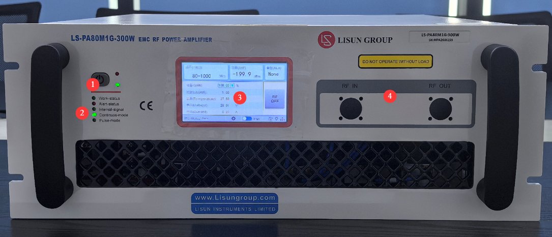
3.1 Front Panel Description
See Figure 3-1.
| Number | Note |
|---|---|
| ① Power Switch | Red light on: Indicates that 220V power is connected and the device is in standby mode. Green light on: Indicates that the device is in operating mode. |
| ② Operating Status Indicator Light | Work-status light: When lit, the device is in normal operating mode. Alert-status light: When lit, the device is in protection mode (over-temperature, standing wave ratio (SWR) exceeded, over-excitation, etc.). Internal-signal light: When lit, the device is using the built-in signal source; A dark indicator means the device is using an external signal source. Continuous-mode indicator: A lit indicator means the device is operating in continuous-wave mode. Pulse-mode indicator: A lit indicator means the device is operating in pulse-wave mode. |
| ③ Touchscreen | No parameters need to be set; the device’s current operating status is displayed. Tap “RF OFF” to toggle between “RF OFF” (radio frequency off) and “RF ON” (radio frequency on). |
| ④ | The RF input and output connectors on the front panel have been removed; please refer to the rear panel of the device. |
3.2 Back Panel Instructions
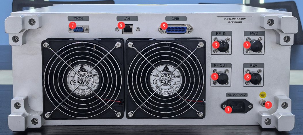
See Figure 3-2.
| Number | Note |
|---|---|
| ① AC Power Outlet | Connect the device to the correct power source |
| ② Grounding Rod | The equipment’s protective grounding terminal must be reliably grounded. |
| ③RF IN | RF signal input port, N-type female connector, 50Ω impedance. Pay attention to the input signal power range to prevent over- or under-excitation. |
| ④ RF OUT | RF output port, N-type female connector, 50Ω impedance. Ensure proper load matching; do not operate without a load. |
| ⑤FWD | Forward power monitoring port, N-type female connector, typical coupling coefficient of 50 dB |
| ⑥REV | Reverse power monitoring port, N-type female connector, typical coupling coefficient of 50 dB |
| ⑦ RS-232 port | Expand Communication Ports |
| ⑧LAN Port | Connects to a PC for communication; default IP address: [192.168.1.200](192.168.1.200), default port: 5000 |
| ⑨GPIB Port | Connects to and communicates with a PC; default address: 12 |
4. Basic Operating Procedures
Startup Procedure
Verify that all connections are correct; the device enters standby mode, and the red light turns on. Press the power switch to start the device, which then enters operating mode—the green light turns on, and the “Continuous-mode” light illuminates. Wait for the device to complete its self-test (approximately 30 seconds), and verify that the display shows normal operation with no alarm messages.
Signal Input Operations
Turn on the signal source and set the output power to the minimum value (it is recommended to start at -30 dBm); gradually increase the signal source’s output power while monitoring the device’s output power display; slowly adjust to the desired output power—never increase Input power suddenly; monitor the device’s status indicators and alarm messages in real time during operation.
Important Note: When connecting a high-power amplifier to a drive signal source, the power of the drive signal source must be strictly limited; otherwise, the amplifier components may be damaged. The drive power must be gradually increased from a low level until the required output power is achieved.
Shutdown Procedure
Set the signal source’s output power to the minimum, then turn off the signal source; press the power switch on the front panel to put the device into standby mode; wait 2 minutes after the device’s cooling fan stops running before turning off the main power; if the device will not be used for an extended period, unplug the power cord.
5. Programmed Commands
| Version: GSMG V6_1 (DW_GD) | |||||
|---|---|---|---|---|---|
| No. | Type | Instructions | Response | Explanation/Examples | |
| Normal | Error | ||||
| 1 | Search | READ PROTECT SWITChn | PROTECT SWITCH ONn PROTECT SWITCH OFFn | NAKn | Read the current protection status |
| 2 | Settings | SET PROTECT SWITCH: XXn | SET PROTECT SWITCH: ONn SET PROTECT SWITCH: OFFn |
NAKn | Protection On (Amplifier Off): SET PROTECT SWITCH: ONn Protection Off (Amplifier On): SET PROTECT SWITCH: OFFn |
| 3 | Settings | RESETn | ACKn | NAKn | Reset the power amplifier; if an alarm is present, clear it; the power amplifier can only be turned on if there are no alarms. |
| 4 | Search | READ PWRn | PWR: xx.xx dBmn | NAKn | Read Real-Time Power |
| 5 | Search | READ SWRn | SWR: x.xx:1n | NAKn | Read Real-Time Standing Wave Ratio |
| 6 | Search | READ ETRn | ETR: NO WARNINGn // No excitation alarm ETR: OVER ETRn // Over-excitation alarm |
NAKn | Read Real-Time Incentives |
| 7 | Search | READ TEMPn | TEMP: +xx.x°Cn | NAKn | Read the real-time temperature |
| 8 | Search | READ WARNn | WARN: NO WARNn // No alarm WARN: OVER SWRn // Standing Wave Ratio (SWR) Overlimit Alarm WARN: OVER ETRn // Over-excitation alarm WARN: OVER TEMPn // Overtemperature alarm Module N fault WARN: Mxxxxxxxxxxxxxxxx |
NAKn | Read Alarm Status |
| 9 | Settings | LINK PCn | ACKn | NAKn | Send this command repeatedly to determine the network connection status. |
| 10 | Settings | SET FRQ: xxxxx.x MHz | ACKn | NAKn | Set the frequency. For example, to set 897 MHz: SET FRQ:00897.0MHzn |
| 11 | Settings | SET STDPOWER: xx.xx dBmn | ACKn | NAKn | Set the standard power (with the internal signal source enabled); for example, to set the standard power to 40 dBm: SET STDPOWER:40.00 dBm |
| 12 | Settings | SET PERIOD: xxxxusn | ACKn | NAKn | Set the period (pulse amplifier); for example, to set the pulse period to 800 us: SET PERIOD:0800usn |
| 13 | Settings | SET DUTYRATIO: xx.xx%n | ACKn | NAKn | Set the duty cycle (pulse amplifier); for example, to set the pulse duty cycle to 1 percent: SET DUTYRATIO:01.00%n |
| 14 | Settings | SET IP: xxx.xxx.xxx.xxxn | ACKn | NAKn | For example, to set the IP address of this machine to 192.168.1.200: SET IP:192.168.001.200n |
| 15 | Settings | SET MAC: XX-XX-XX-XX-XX-XXn | ACKn | NAKn | Set the device’s MAC address; for example, set it to 08-14-28-39-55-60: SET MAC:08-14-28-39-55-60n |
| 16 | Settings | SET SUB: xxx.xxx.xxx.xxxn | ACKn | NAKn | Set the subnet mask for this machine, for example: SET SUB:255.255.255.000n |
| 17 | Settings | SET GW: xxx.xxx.xxx.xxxn | ACKn | NAKn | Set the local gateway, for example: SET GW:192.168.001.001n |
| 18 | Settings | SET PORT: xxxxn | ACKn | NAKn | Set the client’s port number, for example: SET PORT:5000n |
| 19 | Search | READ CLIENT IPn | CLIENT IP: 000.000.000.000n | NAKn | Read the local IP address |
| 20 | Search | READ CLIENT MACn | CLIENT MAC:00-00-00-00-00-00n | NAKn | Read the local physical address |
| 21 | Search | READ CLIENT SUBn | CLIENT SUB:000.000.000.000n | NAKn | Read the local subnet mask |
| 22 | Search | READ CLIENT GWn | CLIENT GW:000.000.000.000n | NAKn | Read the local gateway |
| 23 | Search | READ CLIENT PORTn | CLIENT PORT:0000n | NAKn | Read Client PORT |
| 24 | Settings | SET SOURCE: EXTERNALn // External signal source SET SOURCE: INTERNALn // Internal signal source |
ACKn | NAKn | Set the Signal Source (for amplifiers that support switching between internal and external signals): Internal or External |
| 25 | Settings | SET MODE: AVGn // Continuous wave SET MODE: PEKn // Pulsed wave |
ACKn | NAKn | Operation Mode (for amplifiers that support continuous-pulse operation): Continuous Wave or Pulsed Wave |
| 26 | Search | READ SOURCEn | SOURCE: INTERNALn // Internal signal source SOURCE: EXTERNALn // External signal source |
NAKn | Signal Source: Internal or External |
| 27 | Search | READ MODEn | MODE: AVGn // Continuous Wave MODE: PEKn // Pulsed Wave |
NAKn | Reading Mode: Continuous Wave or Pulsed Wave |
| 28 | Search | READ FRQn | FRQ: xxxx.xMHzn | NAKn | Read Frequency |
| 29 | Search | READ STDPOWERn | STDPOWER: xx.xx dBmn | NAKn | Read Standard Power |
| 30 | Search | READ PERIODn | PERIOD: xxxxusn | NAKn | Read Cycle |
| 31 | Search | READ DUTY RATIO | DUTYRATIO: xx.xx%n | NAKn | Read the duty cycle |
| 32 | Search | READ SCOPE FRQn | FRQ SCOPE: xxxx–xxxx MHz | NAKn | Reading Frequency Range |
| 33 | Search | READ SCOPE STDPOWERn | STDPOWER SCOPE: xx-xx dBmn | NAKn | Read the standard power range |
| 34 | Search | READ SCOPE PERIODn | PERIOD SCOPE: xxxx-xxxxusn | NAKn | Read Cycle Range |
| 35 | Search | READ SCOPE DUTY RATIO | DUTY RATIO SCOPE: xx.xx–xx.xx%n | NAKn | Read the duty cycle range |
| 36 | Search | DEBUG READ POSITIVE VOLTAGE n | VOL_POS: x.xxxVn | NAKn | Debug: Read the forward voltage value |
| 37 | Search | DEBUG READ NEGATIVE VOLTAGE | VOL_NEG: x.xxxVn | NAKn | Debug: Read reverse voltage value |
| 38 | Search | *IDN? n | xxxn | NAKn | Check the Machine Serial Number |
| 39 | Search | READ RPWRn | RPWR: xx.xx dBmn | NAKn | Read Real-Time Reverse Power |
| 40 | Search | READ KBn | Read the current forward and reverse KB values | ||
| 41 | Search | READ SOFTWARE VERSIONn | vX. X. XXn | Read the slave device software version number | |
| 42 | Search | READ ERR SCOPEn | ERR SCOPE: X. XXXXXX | Permissible Range for Power Output Error | |
| 43 | Search | READ NEG GATE_VALn | SWR GATE_VAL: X. XXXXXX | Read the reverse voltage threshold | |
| 44 | Search | Read_RTC_Timen | Current_RTC_Time: November 27, 2018, 10:55 |
Read Internal Time (Only amplifiers with an internal clock support this command) | |
| Note: | |||||
| Ethernet Devices: The Ethernet port uses the TCP/IP protocol. The power amplifier acts as the server, with a default IP address of 192.168.1.200:5000 . Serial devices: Serial port parameters—baud rate 9600, 8 data bits, 1 start bit, 1 stop bit, no parity. |
|||||
6. Daily Maintenance and Care of Equipment
Routine Checkup Items
6.1.1 Daily Pre-Use Inspection
Inspect the power cord for damage or signs of aging; check that the RF connectors are clean and securely connected; check for dust buildup in the equipment’s ventilation openings; verify that the ground connection is secure; after turning on the power, check that the equipment’s self-test runs normally and that there are no alarms.
Weekly Routine Inspection
Clean dust from the surface of the equipment to keep it looking neat; check that the cooling fan is operating normally and listen for any unusual noises; inspect all connectors for looseness or oxidation; verify that all equipment parameters are displayed correctly.
Cleaning and Maintenance
6.2.1 Cleaning the Housing
Turn off the device and unplug the power cord; wipe the device’s exterior with a clean, soft, dry cloth; for stubborn stains, dampen a cloth with a small amount of neutral detergent, wipe the area, and then dry it with a dry cloth; never use organic solvents such as alcohol or gasoline to clean the device’s surface; never allow liquids to enter the device.
Cleaning the Cooling System
Clean the cooling air ducts and fans once every 3 months; use dry compressed air (at a pressure not exceeding 0.5 MPa) to blow into the cooling air intake and remove dust; take care not to damage the fan blades during cleaning; if the fan makes unusual noises or spins at an abnormal speed, contact customer service promptly to have it replaced.
RF Connector Maintenance
Inspect the RF connectors regularly and keep them clean and dry. If the connectors are dirty, gently wipe the contact surfaces with a cotton swab dipped in anhydrous alcohol. When inserting or removing the RF connectors, align them vertically to avoid damaging the threads by inserting them at an angle. Apply moderate force when tightening the connectors to avoid damaging them by over-tightening.
6.3 Storage and Long-Term Preservation
Storage Requirements
The equipment should be stored in a dry, well-ventilated, dust-free environment; storage temperature: -10°C to +50°C; storage humidity: ≤80% RH, no condensation; the equipment should be kept in its original packaging or a dust cover; all RF interfaces should be fitted with protective caps to prevent dust from entering.
Long-Term Storage and Maintenance
When the equipment is stored for an extended period (more than 3 months), it should be powered on once a month; each time it is powered on, it should remain in standby mode for at least 30 minutes to remove internal moisture; periodically inspect the exterior of the equipment for any abnormalities during storage.
6.4 Calibration Interval Requirements
To ensure the measurement accuracy and operational reliability of the equipment, it is recommended that it be sent periodically to a qualified third-party metrology organization for calibration. The recommended calibration interval is 12 months. Users may determine the specific calibration interval based on frequency of use, environmental conditions, and quality system requirements.
7. Troubleshooting and Resolving Common Problems
| Fault Symptoms | Possible Causes | Procedure |
|---|---|---|
| No RF output | Protection function triggered, abnormal input signal, no load connected to RF output | Check to see if the “Alert-status” light is on; try again after troubleshooting. Check whether the signal source is functioning properly, whether the input RF cable is securely connected, and whether the input power is within the normal range. Try again after correctly connecting the matching load. |
| Output power is too low | Insufficient Input power, poor contact at the input connector, reduced gain, operating frequency outside the bandwidth, or excessive temperature causing power reduction | Increase the signal source’s output power; retighten the RF connectors and clean the contact surfaces; if the equipment is aging or component performance has deteriorated, contact the manufacturer for calibration and repair; verify that the operating frequency is within the equipment’s rated frequency range; check that heat dissipation is functioning properly and clean dust from the air vents. |
| Over-Excitation Alarm (OVER ETR) | The input power exceeds the maximum value allowed by the device. | Immediately reduce the signal source’s output power, verify that Input power does not exceed 0 dBm, and then slowly increase Input power from low to high. |
| Standing Wave Ratio (SWR) Alarm (OVER SWR) | Output load mismatch, excessive reflected power | Check whether the output load is connected; check whether the RF cable is damaged; check whether the load is damaged; check whether the standing wave ratio exceeds the specified limit; and verify that the load impedance is 50Ω. |
| Over-Temperature Alarm (OVER TEMP) | The internal temperature of the device has exceeded the protection threshold | Immediately stop high-power output, allow the device to cool down under no-load conditions, check whether the cooling fan is operating normally and whether the cooling vents are clogged with dust, verify that the ambient temperature is not too high, and ensure there is sufficient space around the device for heat dissipation. Once the temperature returns to normal, the system will automatically resume operation or you can manually reset it. |