
 English
 中文简体
中文简体 English
 Русский
 Español
 Português
 Türkçe
 العربية
 Deutsch
 Polski
 Italiano
 Français
 한국어
한국어 ไทย
ไทย Tiếng Việt
 日本語
日本語





























Rotating Barrel Drop Test Machine
User's Manual
Applicable LISUN models: LS-DDT1-A、LS-DDT1-B、LS-DDT2-AB
1. Unboxing and Basic Familiarization with the Equipment
1.1 Key Technical Specifications
| Model | LS-DDT1-B | LS-DDT1-A | LS-DDT2-AB |
| Number of drums | Single-drum | Twin-drum | |
| Drum Width | 275 mm | ||
| Drop Height | B = 500 mm | A = 1000 mm | A = 1000 mm and B = 500 mm |
| Maximum weight of the test item | 5 kg | ||
| Frequency of Falls | 1–20 times per minute (or 2–10 revolutions per minute) | ||
| Number of Tests | 0–999999 times (adjustable) | ||
1.2 Unboxing and Checking the Contents
1.2.1 Unpacking and Visual Inspection
When unpacking the device, handle it gently to avoid scratching the casing with sharp tools. After unpacking, first inspect the exterior of the device to ensure there is no obvious deformation or dents, and that the buttons are not damaged or loose. If you notice any abnormalities with the device or its accessories, do not turn it on. Please contact us immediately.
1.2.2 Main Unit and Accessories
| Number | Note |
| ① | LS-DDT Series Rotating Barrel Drop Test Machine |
| ② | Power Cord |
Download links for the digital user manual, software, warranty card, and other materials have been sent via email. Please download them as soon as possible. If you missed the email, please feel free to contact us to request the download links again.
1.3 Scope of Application
This testing machine strictly complies with GB/T 2423.7-2018 (Clause 5.3, Appendix A) andGB/T 2099.1-2021 (Clause 24.3). It is suitable for conducting repeated free-fall tests on small products such as mobile phones, small electronic devices, and portable accessories. The test simulates damage caused by drops and tumbling during transportation and use to evaluate the product’s drop resistance.
2. Safety Precautions
2.1 Electrical Safety
The device’s input power supply is AC 220 V, 50/60 Hz. Ensure that the power supply matches the specifications on the device’s nameplate. Never connect the device to a voltage other than the rated voltage to prevent short circuits or damage to the device.
The equipment must be properly grounded. Before testing, check that the grounding terminal is securely connected. Do not start the test if the equipment is not grounded to prevent the risk of electric shock.
Before performing equipment maintenance or troubleshooting, you must turn off the power and unplug the power cord to prevent electric shock.
2.2 Operating Procedures
Operators must complete pre-job training and become familiar with the operating procedures outlined in this manual before operating the machine. Unauthorized personnel are strictly prohibited from operating the machine.
After placing the sample in the drum chamber, ensure that the door is closed and locked before starting the equipment.
While the equipment is in operation, operators must not reach into the drum compartment with their hands, arms, or any other body parts, and opening the drum compartment door is strictly prohibited.
While the equipment is in operation, do not enter the drum’s rotation area, and do not place any foreign objects within the drum’s rotation area.
2.3 Environment and Protection
The equipment should be used in a dry, well-ventilated environment free of corrosive gases, with an ambient temperature of 0–40°C and relative humidity of ≤85%. Avoid moisture or excessive dust, which can cause equipment malfunctions.
Do not cover the ventilation openings while the equipment is running, and do not place flammable or explosive materials near the equipment. If an alarm sounds, stop the test immediately and restart the equipment only after the problem has been resolved.
2.4 Other
For matters not covered in this manual, please proceed with caution or contact us.
3. Equipment Overview
3.1 Equipment Appearance
The LS-DDT1 series Rotating Barrel Drop Test Machine is shown in the figure below.
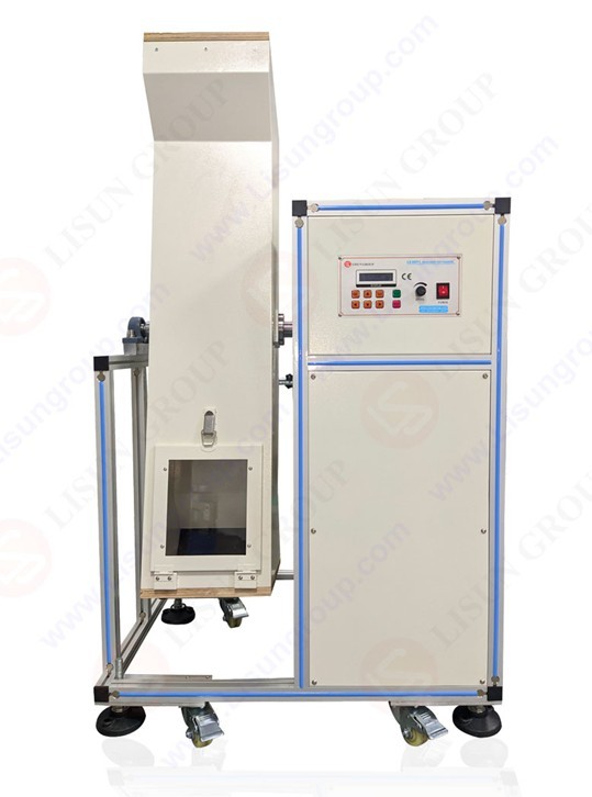
Figure 1
The LS-DDT2 rotating barrel drop test machine is shown in the figure below.
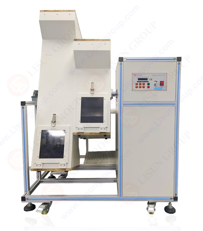
Figure 2
3.2 Control Panel
| Project | Note |
| POWER | Power Button: Turns the testing machine on or off |
| CLR | Reset button: Pressing this button will reset the number of tests performed. |
| SET | Press the Settings button to switch from normal mode to edit mode, adjust the number of test runs, and finally confirm and return to normal mode. |
| Arrow keys: Up | Numerically Ascending Key |
| Arrow keys: Down | Descending Numeric Keys |
| Arrow keys: Left | Left Shift key: Use this to switch between settings when configuring the interface. |
| Arrow key: Right | Right Shift key: Use this to switch between settings when configuring the interface. |
| RUN | Start button, start the drum drop test |
| SPEED | Drum Speed Controller: Adjusts the drum rotation speed. Note: The device has been factory-set according to standards and does not require further adjustment. If you need to use a different speed, please start the test and adjust the speed gradually. |
| STOP | Stop button, stop the test |
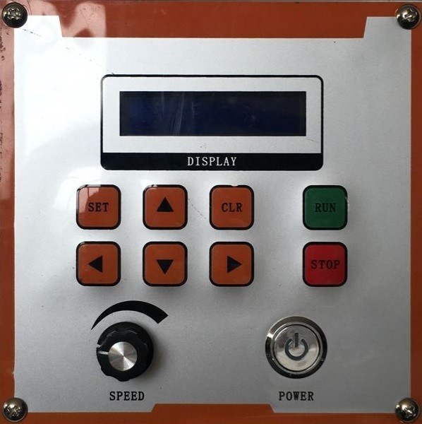
Figure 3
4. Introduction to the Screen Display
4.1 Startup Display
| Project | Note |
| SP | Drum rotation speed, revolutions per minute |
| TM | Number of tests set |
| ADD TIMES | Number of Tests Performed |
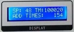
Figure 4
4.2 Settings Interface
| Procedure | Note |
| ① | While the device is in standby mode, press the Settings button to enter the settings menu. |
| ② | Use the up and down arrow keys to change the “MODEL” counting mode; 0 indicates forward counting, and 1 indicates backward counting. |
| ③ | Press the left or right arrow keys again to access the “TIMES” setting for the number of tests. Move to the position you want to change, then press the up or down arrow keys to increase or decrease the value. |
| ④ | Once all settings are configured, press the Settings button again to exit setup mode. |
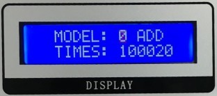
Figure 5
5. Preparations Before the Test
5.1 No-Load Test Run
Press the power button to turn on the screen, and check for any display abnormalities, such as a black screen or distorted image;
Follow the instructions in Section 4.2 to set the counting method and the number of tests; once set, return to the initial screen;
Press the Reset button to reset the actual count to zero, then press the Start button to start the device, which will enter idle mode;
Observe that the drum runs smoothly, with no vibration, unusual noises, or jamming, and that the buttons on the control panel respond promptly;
At the same time, verify that the drum speed displayed on the screen is as expected. If necessary, slowly turn the drum speed adjuster to bring the drum speed in line with the specified requirements;
After confirming that the equipment is running normally without a load, press the Stop button to stop the drum from rotating.
5.2 Sample Preparation
5.2.1 Sample Verification
Verify that the weight of the sample under test is ≤5 kg and that its dimensions match the drum width. Testing of samples that exceed the weight or size limits is strictly prohibited;
Record the original condition of the sample, including its appearance, structure, and functionality, to facilitate comparative analysis after testing.
5.2.2 Sample Placement
When the device is turned off or in standby mode, open the drum door and gently place the sample into the drum;
Ensure that the sample is not jammed inside the chamber and will not be crushed or scraped when the drum rotates;
Close and lock the drum door, ensuring it is secure to prevent it from opening during the test.
6. Drum Drop Test
6.1 Startup Test
Press the “Reset” button to reset the number of tests;
Press the start button to turn on the device; the drum will run at the preset speed, and the screen will display the cumulative number of actual test cycles in real time;
After the equipment starts running, observe the drum’s rotational speed. If there is a deviation from the target speed, slowly adjust the speed control knob until the correct speed is reached;
During the test, monitor the condition of the sample in real time through the drum’s observation window to ensure that the sample is not jammed, damaged, or exhibiting any other abnormalities (if the test is intended to assess maximum drop resistance, normal wear and tear may be disregarded).
6.2 Monitoring the Test Process and Handling Anomalies
Check the equipment’s operating status every 10 minutes to ensure that the drum speed is stable, there are no unusual noises, and the screen count is normal;
If you need to check a sample temporarily, press the Stop button; the device will immediately halt the test, and the count displayed on the screen will remain unchanged. Once the check is complete, press the Start button to resume the test, and the count will continue from the value at which it was paused.
7. Post-Test Procedures
7.1 Normal Shutdown Procedure
When the number of tests performed on the screen matches the preset number, the device will automatically shut down and enter standby mode;
Press the reset button to clear the actual count and prepare for the next test;
7.2 Early Termination
If you need to terminate the test early due to testing requirements, press the Stop button to halt the machine, record the actual number of tests completed as shown on the screen, then press the Reset button to clear the count, and finally press the Power Off button.
7.3 Sample and Equipment Preparation
7.3.1 Sample Preparation
After the equipment has come to a complete stop, open the drum door and carefully remove the sample;
Record the condition of the sample after testing, compare it to its original condition, and complete the test report.
7.3.2 Equipment Organization
Remove any foreign objects and debris from the drum chamber, and wipe down the sliding surfaces and rubber wedges inside the chamber with a clean, soft cloth;
Close and lock the drum door;
If you won’t be using the device for an extended period of time, unplug it and take measures to protect it from dust.
7.4 Interpretation of Test Results
GB/T 2423.7-2018 General Evaluation Requirements:
Visual Inspection: No obvious damage, deformation, cracks, etc.; Mechanical Performance Testing: Structural integrity, component tightness, operational flexibility, etc.; Electrical Performance Testing: Insulation resistance, electrical continuity, functional integrity, etc.
GB/T 2099.1-2021 Criteria for Determination:
Electric Shock Protection: After testing, the socket’s electric shock protection performance shall not be reduced, and live parts shall remain inaccessible; Mechanical Strength: There shall be no damage that affects use; Electrical Performance: The insulation resistance shall meet the standard requirements (typically ≥1 MΩ); there shall be no electrical faults such as short circuits or open circuits; grounding continuity shall remain good; Functional Integrity: Plugs shall be able to be inserted into and removed from the outlet normally, and the contacts shall be reliable.
8. Daily Maintenance and Care of Equipment
8.1 Routine Cleaning (Performed After Each Test)
Control Panel: Wipe the control panel, screen, and exterior of the unit with a dry cloth. Do not use a damp cloth under any circumstances to prevent electrical short circuits;
Drum Test Apparatus: Wipe the outer surface of the drum, the door, and the observation window with a clean, soft cloth. Wipe the interior of the drum with a dry cloth or an antistatic cloth, taking care not to scratch the plastic sliding surfaces;
Clear away any clutter around the equipment and keep the equipment’s operating area clean and tidy.
8.2 Regular Lubrication (Once a month or after 50 hours of operation)
After turning off the power to the device and unplugging the power cord, open the protective cover on the mechanical connection of the device;
For mechanical components subject to high operational loads—such as drum shafts, bearings, and gears—apply lubricating oil. The amount applied to each area should be sufficient to cover the component’s surface, but avoid applying so much that it overflows;
8.3 Long-Term Storage
If the device will not be used for an extended period, store it in a dry, well-ventilated area, away from moisture and direct sunlight;
Disconnect all cables, store the accessories separately, and cover the device with a dust-proof cloth;
Turn on the device for 30 minutes each month to prevent the internal electronic components from deteriorating and to verify that the device is functioning properly.
9. Troubleshooting and Resolving Common Problems
This section provides a simple troubleshooting guide intended to help operators resolve common issues on their own. If the problem cannot be resolved, or if it involves the device’s internal circuitry or core mechanical components, contact us immediately. Under no circumstances should you disassemble or repair the device yourself; doing so will void the warranty. Before performing any troubleshooting, be sure to turn off the device and unplug the power cord.
9.1 Power-Related Faults
| Fault Symptoms | Possible Causes | Procedure |
| After pressing the power button, the screen flickers and the device fails to start up. | 1. Unstable power supply voltage; 2. Poor power supply grounding | 1. Replace the power outlet with a stable one, and avoid sharing the same outlet with high-power devices; 2. Verify that the power outlet is properly grounded, and reconnect the ground wire. |
9.2 Display-Related Malfunctions
| Fault Symptoms | Possible Causes | Procedure |
| Screen settings are not saved; they revert to default values when the device is turned on. | The setting has not been confirmed, or the internal battery of the counter is dead. | 1. Reset the parameters and press the SET button to confirm and exit; 2. If the settings still do not save, the counter battery is dead. Please contact us to have the battery replaced. |
9.3 Operational Faults
| Fault Symptoms | Possible Causes | Procedure |
| Screen settings are not saved; the device reverts to default settings when it starts up. | The setting has not been confirmed, or the counter’s internal battery is dead. | 1. Reset the parameters and press the SET button to confirm and exit; 2. If the settings still do not save, the counter battery is dead. Please contact us to have the battery replaced. |