
 English
 中文简体
中文简体 English
 Русский
 Español
 Português
 Türkçe
 العربية
 Deutsch
 Polski
 Italiano
 Français
 한국어
한국어 ไทย
ไทย Tiếng Việt
 日本語
日本語





























Conduits Compression Test Apparatus
User's Manual
Applicable LISUN models: LS-B50
1. Basic Understanding of Equipment
1.1 Key Parameters
1.1.1 Equipment Technical Specifications
| Parameters | Note |
| Maximum Pressure | 5000 N |
| Pressure Accuracy | ±1% |
| Specifications for Pressurized Steel Blocks | 50 × 50 mm |
| Steel Base Dimensions | 300 × 150 mm |
| Lifting Range | 200 mm |
1.1.2 Applicable Standards
The LS-B50 Conduits Compression Test Apparatus is designed and manufactured in strict accordance with Clause 10.2 and Figure 1 (IEC 61386-1:2017, Clause 10.2, Figure 1).
1.2 Equipment Configuration Verification
1.2.1 Unpacking
When unpacking the device, handle it gently to avoid scratching the casing with sharp tools. After unpacking, first inspect the exterior of the device to ensure there is no visible deformation or dents, and that the buttons are not damaged or loose. If you notice any abnormalities with the device or its accessories, do not turn it on. Please contact us immediately.
1.2.2 Main Unit and Accessories
| Number | Note |
| ① | LS-B50 Main Unit |
| ② | Power Cord |
1.2.3 Downloading Electronic Documents
We have already sent the download links for the electronic user manual, calibration certificate, warranty card, and other documents via email at the time of shipment. Please download them as soon as possible. If you have not received the email, please contact us to request the download links again.
2. Safety Precautions
2.1 Electrical Safety
Before connecting the power cord, verify that the supply voltage is AC 220 V ±10% and the frequency is 50 Hz or 60 Hz. You must use a three-prong outlet with a protective ground, and the protective ground resistance must be ≤4 Ω. Never cut or disconnect the protective ground wire, as doing so poses a risk of electric shock.
2.2 Environmental Safety
Do not use in environments with flammable or explosive substances, strong electromagnetic interference, high temperatures and humidity, or excessive dust levels. Place the equipment on a level, stable surface, and ensure there is at least 0.5 m of operating space around it. Operating environment: temperature 15°C to 35°C, relative humidity 45% to 75%.
2.3 Operating Procedures
During testing, do not place your hands or any other part of your body within the pressure test area to prevent injuries from being crushed; test specimens must be securely fastened to prevent them from falling and causing safety incidents during testing; it is strictly prohibited to disassemble the equipment’s transmission mechanism or dismantle the machine without authorization.
3. Equipment Overview
3.1 Standard Diagram
See Figure 3-1 (taken from the IEC standard).
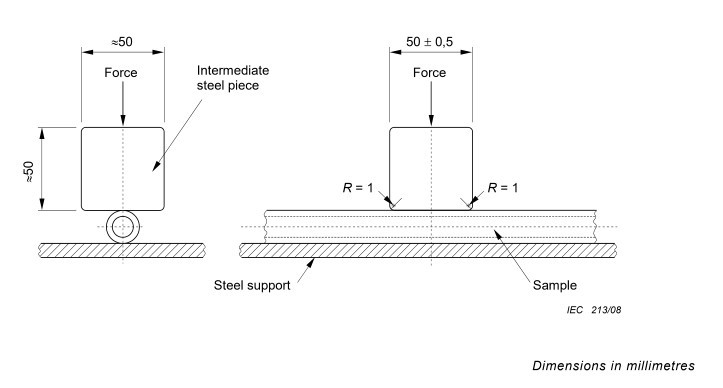
Figure 3-1
3.2 Product Photos
See Figure 3-2.
| Number | Note |
| ① | Power Switch |
| ② | Buzzer; a buzzer sounds when the test is complete. |
| ③ | Touchscreen |
| ④ | Pressure block, used to apply pressure to the conduit specimen |
| ⑤ | Pressure Sensor |
| ⑥ | Steel Base |
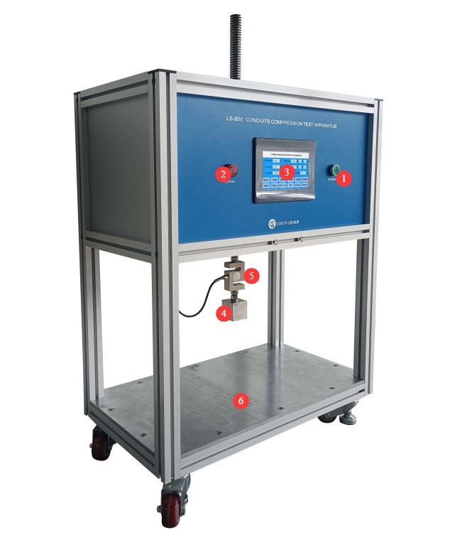
Figure 3-2
4. Introduction to the Touchscreen Program
4.1 Initial Screen
See Figure 4-1.
| Number | Note |
| ① | Test Interface, Chinese |
| ② | Test Interface, English |
| ③ | Pressure Calibration Interface, Chinese |
| ④ | Pressure Calibration Interface, English |
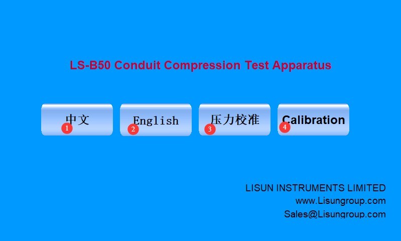
Figure 4-1
Note: The pressure readings have been calibrated before the device left the factory. If you need to recalibrate the pressure during use and have any questions about operating the calibration interface, please contact us.
4.2 Test Interface
See Figure 4-2.
| Number | Note |
| ① | To preset the load pressure value, click the ⑧ Pressure Value button. Do not set non-standard pressure values on your own. |
| ② | Set the test duration; according to the standard, it should be set to 60 seconds. |
| ③ | Current Load Pressure Value |
| ④ | Current Test Duration |
| ⑤ | Number of loading pulses, preset according to different pressure values |
| ⑥ | Time from 0 to the preset pressure value |
| ⑦ | Reset, Release Pressure |
| ⑧ | Pressure values for different catheters—simply click to preset them |
| ⑨ | Start/Stop Test |
| ⑩ | Reset: Clear the data from the last test and clear the beep alarm. |
| ⑪ | Reset the pressure value; set the current force value to 0 |
| ⑫ | Up—click to raise the steel block |
| ⑬ | Drop; click to lower the steel block |
| ⑭ | Return to the Home Screen |
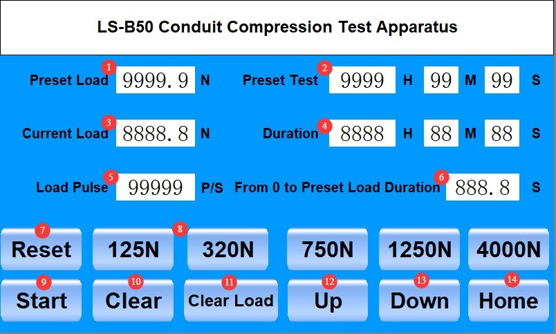
Figure 4-2
5. Pressure Testing of Electrical Conduits
5.1 Preparations
5.1.1 Preparation of Test Specimens
Cut a test specimen from the conduit with a length of (200±5) mm. Maintain the test environment temperature at (23±2) °C. Before the test, measure the outer diameter of the conduit specimen.
5.1.2 Determination of Pressure Values
| Classification Code | Catheter Types | Pressure N (tolerance ±4%) |
| 1 | Ultra-light | 125 |
| 2 | Light | 320 |
| 3 | Chinese | 750 |
| 4 | Heavy | 1250 |
| 5 | Overweight | 4000 |
5.1.3 Positioning of Test Specimens and Equipment
Place the pipe specimen on the steel base, click “Up/Down” to move the steel block toward the pipe specimen. Stop just before contact is made, then click to reset the pressure reading to zero.
5.2 Pressure Test Procedures
5.2.1 Normal Test Procedure
Set the test duration to 60 seconds. Refer to Section 5.1.2, click the button for the desired pressure value to preset the pressure value and loading pulse, and then click “Start” to begin the test.
After the test begins, the steel block slowly applies pressure to the guide tube. When the pressure value begins to change, the timer starts counting the time from 0 until the preset pressure value is reached. When the current pressure value reaches the preset pressure value, the timer stops counting the time from 0 until the preset pressure value is reached, and the timer begins counting the current test duration.
When the current test duration reaches the preset test duration, the device sounds an alarm, but the current pressure value remains at the preset pressure value. According to the standard, after the test is complete, the outer diameter of the specimen at the flattened section must be measured without relieving the pressure. The difference between the original outer diameter and the outer diameter of the specimen after flattening must not exceed 25% of the original outer diameter measured before the test.
Click “Reset” to release the pressure and return the steel block to its initial position. After (60±2) seconds, measure the outer diameter of the flattened portion of the specimen again. The difference between the original outer diameter and the outer diameter of the flattened specimen must not exceed 10% of the outer diameter measured before the test.
After the test, the test specimen must not exhibit any cracks visible to the naked eye or with corrected vision without any additional magnification.
5.2.2 Debugging Load Pulses
Depending on the catheter’s compressive strength, the preset loading pulses may require adjustment. During normal testing, if the timer stops while the load is being applied from 0 to the preset pressure value and the duration is not within the range of (30±3) seconds, the number of loading pulses must be adjusted.
Taking 4000 N as an example, the corresponding preset number of loading pulses is 2700. If the actual loading duration is 25 seconds, which is less than the standard requirement of (30±3) seconds, you can change the number of loading pulses from 2700 to 2600 and try again; If the actual loading duration is 35 seconds—which exceeds the standard requirement of (30 ± 3) seconds—then try changing the number of loading pulses from 2700 to 2800. Continue adjusting until the loading duration meets the standard requirement.
6. Daily Maintenance and Care of Equipment
6.1 Daily Maintenance After Shutdown
At the end of each day’s testing, clean dust and specimen debris from the equipment surfaces, and keep the steel blocks and steel bases clean and free of debris; use a special touchscreen cleaning cloth to clean the touchscreen; check the pressure-applied steel blocks for deformation or displacement.
6.2 Weekly Routine Maintenance
Apply a small amount of special-purpose lubricating grease to the equipment’s drive lead screw to ensure smooth, jam-free operation.
6.3 Maintenance During Long-Term Storage
After the equipment has been powered off and routine maintenance has been completed, cover the entire unit with a dust cover and store it in a dry, well-ventilated warehouse; power it on for 30 minutes each month to prevent components from being damaged by moisture.
6.4 Calibration Interval Requirements
To ensure the measurement accuracy and operational reliability of the equipment, it is recommended that it be sent periodically to a qualified third-party metrology laboratory for calibration. The recommended calibration interval is 12 months. Users may determine the specific calibration interval based on frequency of use, environmental conditions, and quality system requirements.
7. Troubleshooting and Resolution of Common Problems
| Fault Symptoms | Possible Causes | Procedure |
| Touchscreen lags; taps don’t register | Screen surface smudges causing interference, program crashes | Turn off the device, clean the screen, then restart it and try again. |
| No pressure reading is displayed for an extended period after the test starts | The specimen guide tube was not positioned beneath the steel block, and the steel block was too far from the specimen guide tube. | Reposition the specimen guide tube; use the down arrow key to move the steel block closer to the specimen guide tube, then try again. |
| The load time is not within the (30±3)s range. | Since catheters have different compressive strength, the preset loading pulses may need to be adjusted. | Follow the instructions in Section 5.2.2 for debugging. |
| Pressure Drift | After the equipment has been in use for a long time, it is important to calibrate the force readings. | We recommend having the equipment calibrated by a third-party metrology organization. You can adjust the pressure reading by accessing the calibration screen. |