
 English
 中文简体
中文简体 English
 Русский
 Español
 Português
 Türkçe
 العربية
 Deutsch
 Polski
 Italiano
 Français
 한국어
한국어 ไทย
ไทย Tiếng Việt
 日本語
日本語





























Wireless Charging Foreign Object Temperature Rise Test Kit
User's Manual
Applicable LISUN models: LS-B29
1. Basic Understanding
1.1 Scope of Application
Suitable for foreign object temperature rise safety testing of products such as wireless charging transmitters, in-vehicle wireless charging modules, desktop wireless charging stands, and portable wireless charging devices.
It is primarily used in scenarios such as preliminary testing for laboratory R& D, routine factory acceptance testing, third-party quality inspection and compliance testing, and pre-certification testing for product safety standards.
1.2 Applicable Standards
Designed and manufactured in strict accordance with Clause 9.6 of GB/T 4943.1-2022 (IEC 62368-1:2023), “Audio, Video, Information Technology, and Telecommunications Equipment—Part 1: Safety Requirements.”
Conduct temperature rise compliance tests using metal foreign objects of standard materials and dimensions.
1.3 Test Principles
Place a standard metal foreign object in the wireless charging coupling area in accordance with the standard; use a Type K thermocouple to collect real-time data on the temperature rise of the metal foreign object to determine whether it meets the safety standard temperature rise limits.
1.4 Downloading Electronic Documents
We have already sent the download links for the electronic user manual, calibration certificate, warranty card, and other documents via email at the time of shipment. Please download them as soon as possible. If you have not received the email, please contact us to request the download links again.
2. Precautions for Use
2.1 Operating Environment Safety Requirements
Standard operating environment temperature: 25°C ± 5°C; relative humidity: 45%–75%; no condensation, no corrosive gases, no dust or airborne particulates, and no flammable or explosive materials.
2.2 Safety Guidelines for Operational Procedures
Standard metal foreign objects have sharp edges; wear cut- and scratch-resistant gloves when handling or placing them to prevent accidental injury.
Metal foreign objects may become very hot during testing. Do not touch metal foreign objects or the test area with your bare hands while testing is in progress.
3. Introduction to the Test Suite
3.1 Standard Diagram (Taken from the IEC Standard)
Steel plate; see Figure 3-1.
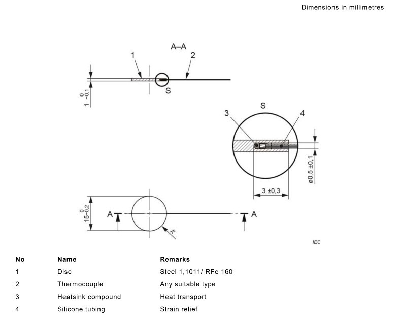
Figure 3-1
Aluminum ring; see Figure 3-2
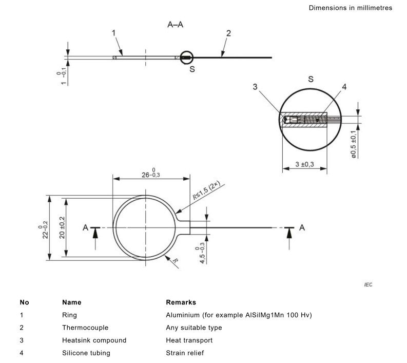
Figure 3-2
Aluminum foil; see Figure 3-3.
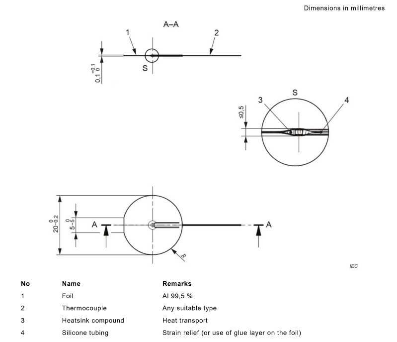
Figure 3-3
3.2 Product Photos
See Figures 3–4.
| Number | Note |
| ① | Steel Plates and Thermocouples |
| ② | Aluminum Rings and Thermocouples |
| ③ | Aluminum Foil and Thermocouples |
| ④ | Non-conductive dielectric sheets, 2 mm and 5 mm thick |
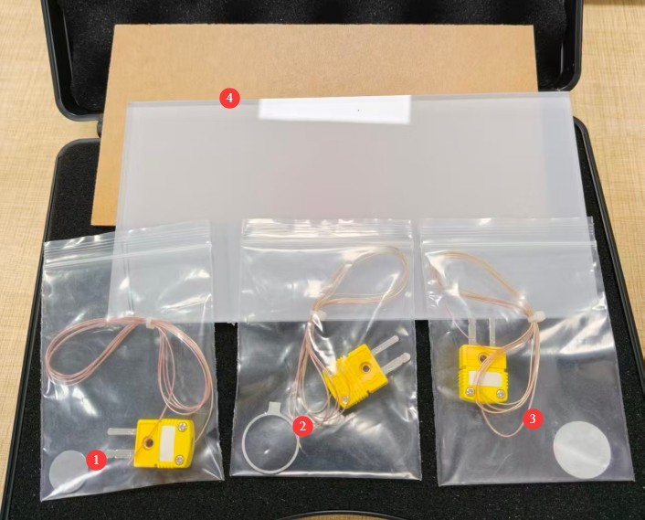
Figure 3-4
Note: All thermocouples are Type K thermocouples.
4. Temperature Rise Test for Foreign Objects During Wireless Charging
4.1 Preparations
4.1.1 Connecting Thermocouples to Metal Foreign Objects
To facilitate customer calibration, the thermocouple is not connected to the metal object when the product leaves the factory. If calibration of the kit is not required prior to testing, please use the adhesive specified for temperature rise tests and follow the standard to connect the thermocouple to the metal object.
4.1.2 Connecting The Multiplex Temperature Tester
Connect the other end of the thermocouple to your Multiplex Temperature Tester to track the thermocouple temperature in real time.
4.2 Test Methods and Acceptance Criteria (IEC Standards)
The wireless power transmitter is placed indoors, and the room temperature is set in accordance with the provisions of Section 9.3.2 of the standard, namely 25°C ± 5°C.
The test consists of two parts (Part A and Part B). In each part, the center of the receiving coil should be aligned with the center of the transmitting coil. Long-distance testing typically requires the use of 2-mm and 5-mm spacers (non-conductive dielectric plates). The frame (if used) and the spacers can be integrated into a single unit.
Secure the metal foreign object, transmitter, and receiver within the frame using a reliable method specified in the standard. In each cycle, move the metal foreign object on the transmitter to determine the maximum temperature.
Part A: The test method involves turning on the transmitter and then bringing each metal foreign object into direct contact with the transmitter. This part consists of four cycles: no receiver, with the foreign object in direct contact with the transmitter; the receiver in direct contact with the foreign object; the receiver at a vertical distance of 2 mm from the foreign object; and the receiver at a vertical distance of 5 mm from the foreign object.
Part B: The test procedure is as follows: First, place each metal foreign object in direct contact with the transmitter, then activate the transmitter. Next, repeat the four cycles described in Part A.
During the tests in Parts A and B: the temperature of foreign objects shall not exceed 85 °C for the copper plate, 120 °C for the aluminum ring, or 155 °C for the aluminum foil; furthermore, the temperature of the transmitter shall not exceed the TS2 limit specified in Table 37 of this standard.
Note 1: The test is not intended to measure the receiver’s temperature; therefore, any compatible receiver capable of extracting the maximum power from the wireless power transmitter may be used, and there is no need to monitor the receiver’s temperature.
Note 2: It is recommended to set the test duration to at least 30 minutes and to record temperature changes throughout the entire process. Once the temperature change remains ≤1°C for two consecutive readings (10 minutes apart), the sample is considered to have reached thermal stability; at that point, the test may be stopped and the current temperature recorded.
5. Post-Test Procedures
5.1 Sample Preparation
Separate the samples that passed and failed the test, label them clearly, and avoid any confusion.
5.2 Metal Foreign Objects and Thermocouple Storage
Once the standard metal foreign objects have cooled to room temperature, wipe them clean and place them in a special storage box containing a desiccant to prevent moisture and rust.
6. Routine Maintenance and Care
6.1 Regular Maintenance
Every 3 months, use a vernier caliper to check the diameter, length, width, and thickness of the metal standard foreign objects; replace them immediately if any deformation exceeds the specified limits.
6.2 Calibration Interval Requirements
To ensure the accuracy and reliability of the device, it is recommended that it be sent periodically to a qualified third-party metrology laboratory for calibration. The recommended calibration interval is 12 months. Users may determine the specific calibration interval based on frequency of use, environmental conditions, and quality system requirements.
7. Troubleshooting and Resolving Common Problems
| Failure Symptoms | Possible Causes | Procedure |
| Abnormal Temperature Display | Abnormal connection between the thermocouple and the metal, or damage to the thermocouple | Check the thermocouple connections; or try again after replacing the thermocouple. |