
 English
 中文简体
中文简体 English
 Русский
 Español
 Português
 Türkçe
 العربية
 Deutsch
 Polski
 Italiano
 Français
 한국어
한국어 ไทย
ไทย Tiếng Việt
 日本語
日本語





























Insulating Sleeves of Plug Pins Abnormal Heat Resistance Test Device
User's Manual
Applicable LISUN models: LS-B17
1. Basic Understanding of Equipment
1.1 Key Parameters
1.1.1 Equipment Technical Specifications
| Parameters | Note |
| Insulation Board | A flat, circular surface 5 mm thick, with a diameter twice that of the specimen’s contact surface, made of bakelite/epoxy board |
| Metal Part B (Fixture) | Length greater than 20 mm; made of brass; comes standard with three types: GB6A two-pin, GB10A three-pin, and GB16A three-pin; customizable |
| Gap between the insulating board and metal part B | 3 ± 0.2 mm, to ensure air circulation around the pins |
| Distance from the thermocouple to the front surface of metal part B | 7 ± 0.5 mm |
| The pin on metal part B is inserted into the hole | Greater than the maximum cross-sectional dimension of the pin by 0.1 mm |
| Temperature Control | Type K Thermocouple with High-Precision Digital Temperature Controller |
1.1.2 Applicable Standards
The LS-B17 Insulating Sleeves of Plug Pins Abnormal Heat Resistance Test Device strictly complies with GB/T 2099.1-2021″Plugs and Sockets for Household and Similar Purposes—Part 1: General Requirements,” specifically Clause 28.1.3 and Figure 40 (IEC 60884-1:2022, Clause 28.1.3, Figure 43).
It is primarily used in electrical product quality inspection laboratories, the quality control departments of manufacturers of electrical accessories such as plugs and sockets, third-party testing organizations, and for import and export product inspections.
1.2 Equipment Configuration Verification
1.2.1 Unpacking
When unpacking the device, handle it gently and avoid using sharp tools that could scratch the outer casing. After unpacking, first inspect the exterior of the device to ensure there is no visible deformation or dents, and that the buttons are not damaged or loose. If you notice any abnormalities with the device or its accessories, do not power it on. Please contact us immediately.
1.2.2 Main Unit and Accessories
| Number | Note |
| ① | LS-B17 Main Unit |
| ② | Power Cord |
1.2.3 Downloading Electronic Documents
We have already sent the download links for the digital user manual, calibration certificate, warranty card, and other documents via email at the time of shipment. Please download them as soon as possible. If you have not received the email, please contact us to obtain the download links again.
2. Safety Precautions
2.1 Electrical Safety
Before connecting the power cord, verify that the supply voltage is AC 220V ±10% and the frequency is 50 Hz or 60 Hz. You must use a three-prong outlet with a protective ground, and the protective ground resistance must be ≤4 Ω. Never cut or disconnect the protective ground wire, as doing so poses a risk of electric shock.
2.2 Environmental Safety
Do not use this equipment in environments with flammable or explosive materials, strong electromagnetic interference, high temperatures and humidity, or excessive dust levels. Place the equipment on a level, stable surface, leaving a minimum of 0.5 m of clearance around it for operation. Operating environment: Temperature 5°C to 35°C, humidity ≤65% RH.
2.3 Operating Procedures
During testing, do not extend any body parts or foreign objects into the equipment’s test area to prevent burns or accidents; do not disassemble equipment components without authorization; set the test temperature strictly in accordance with standard requirements, and do not conduct tests at non-standard temperatures without authorization.
3. Equipment Overview
3.1 Standard Diagram
See Figure 3-1 (taken from the IEC standard).
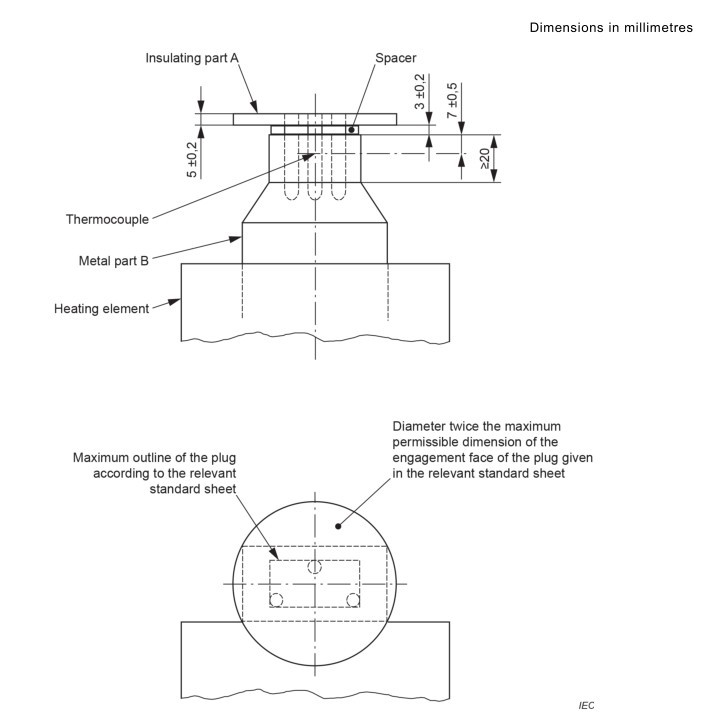
Figure 3-1
3.2 Product Photos
See Figure 3-2.
| Number | Note |
| ① | Power Switch |
| ② | Time display: The top line shows the current test duration, and the bottom line shows the set duration. |
| ③ | Temperature display: The top line shows the current temperature, and the bottom line shows the set temperature. |
| ④ | Stop Test Button |
| ⑤ | Start Test Button |
| ⑥ | Reset Button |
| ⑦ | Mounting Holes for Test Specimen Pins |
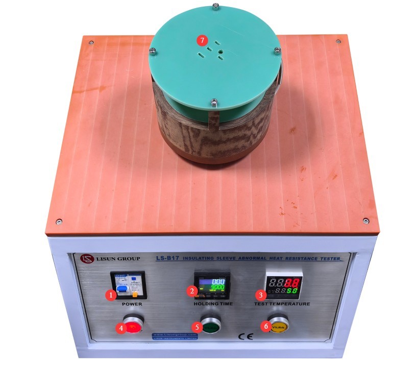
Figure 3-2
4. Insulation Sleeve for Plugs—Abnormal Heat Resistance Test
4.1 Sample Preparation
Select brand-new, original plugs and prongs with intact insulation sheaths that show no cracks or signs of aging; exclude test specimens with damaged sheaths or deformed prongs.
4.2 Set Parameters and Start the Test
| Procedure | Note |
| ① | Set the test duration and temperature according to the standard. For plugs with a rated current of 2.5 A, the test temperature is 120°C; for plugs with a higher rated current, the test temperature is 180°C. The test duration is 3 hours (set to 180 minutes on the equipment). |
| ② | Without loading a specimen, press the “Start Test” button to activate the heating function. This step is used solely to bring the test apparatus up to the test temperature; it takes approximately 40 minutes for the test apparatus to reach 180°C. |
| ③ | After heating the unit under no-load conditions to the set temperature and maintaining that temperature for 10 minutes, insert the test specimen into the testing apparatus, press the reset button, and restart the timer. |
| ④ | When the test duration reaches the set time, the test stops automatically and the heating function turns off. Remove the specimen from the test apparatus, allow it to cool to room temperature, and then hold it at room temperature for at least 4 hours. |
4.3 Post-Test Procedures
4.3.1 Test Specimen Pin
The insulating sheath of the test specimen plug shall comply with the provisions of Clause 30 of the reference standard; however, the impact test and visual inspection shall be conducted at ambient temperature. During the visual inspection, no cracks visible to the naked eye—with or without corrective lenses—shall be present, and any dimensional changes in the insulating sheath shall not be sufficient to compromise protection against accidental contact.
4.3.2 Test Setup
After all tests are completed, the test apparatus will still be at a high temperature; routine maintenance may not be performed until it has cooled to room temperature.
5. Daily Maintenance and Care of Equipment
5.1 Daily Maintenance After Shutdown
Remove dust and test residue from the surface of the equipment, and ensure that the sample mounting holes are clean and free of foreign objects.
5.2 Maintenance During Long-Term Storage
After powering down and cleaning the equipment, cover the entire unit with a dust cover and store it in a dry, well-ventilated warehouse; power it on for 30 minutes each month to prevent components from becoming damaged due to moisture.
5.3 Calibration Interval Requirements
To ensure the measurement accuracy and operational reliability of the equipment, it is recommended that it be sent periodically to a qualified third-party metrology laboratory for calibration. The recommended calibration interval is 12 months. Users may determine the specific calibration interval based on frequency of use, environmental conditions, and quality system requirements.