
 English
 中文简体
中文简体 English
 Русский
 Español
 Português
 Türkçe
 العربية
 Deutsch
 Polski
 Italiano
 Français
 한국어
한국어 ไทย
ไทย Tiếng Việt
 日本語
日本語





























Compression Test Device
User's Manual
Applicable LISUN models: LS-B08
1. Basic Understanding of Equipment
1.1 Basic Properties
This device is specifically designed for mechanical compression testing of plug and socket products. It simulates the conditions under which plugs and sockets are subjected to squeezing and heavy pressure during actual use, and tests the structural strength of the products and the compression resistance of their insulated housings in accordance with national and international standards.
It is primarily used in electrical product quality inspection laboratories, the quality control departments of plug and socket manufacturers, third-party testing organizations, and for the inspection of products entering or leaving the country.
1.2 Applicable Standards
Strictly in accordance with the last paragraph of Clause 10.1, Clause 24.6, and Figure 8 (IEC 60884-1:2022, the last paragraph of Clause 10.2, Figure 6, and Clause 24.6).
Apply a vertical compressive force to the plug and receptacle specimens in accordance with the pressure values and application duration specified in the standard; observe the specimens’ deformation and damage; and determine whether they meet the standard requirements.
1.3 Test Principles
1.3.1 The Principle of Mechanical Pressure
A mechanical gravity-loading mechanism that uses a turntable to drive weights delivers a standard, constant load applied vertically to the surface of the plug and receptacle at the angle specified by the standard.
1.3.2 Principles of Qualitative Testing
After the force application time specified in the standard has elapsed, inspect the appearance of the plug and receptacle and determine whether their hardness and mechanical strength meet the requirements of national and international standards.
1.4 Downloading Electronic Documents
We have already sent the download links for the electronic user manual, calibration certificate, warranty card, and other documents via email at the time of shipment. Please download them as soon as possible. If you have not received the email, please contact us to request the download links again.
2. Precautions for Use
2.1 Operating Environment Safety Requirements
Operating environment temperature: Relative humidity 45%–75%, no condensation, no corrosive gases, and no dust or airborne particles.
Place the device on a level, stable workbench, leaving at least 30 cm of working space on all sides, and keep it away from sources of vibration.
2.2 Safety Guidelines for Operators
During testing, do not insert your hands or fingers into the pressure-applying mechanism to prevent crush injuries.
Samples must be securely positioned to prevent them from falling or ejecting during loading, which could pose a safety hazard.
It is strictly prohibited to exceed the equipment’s rated load by adding weights without authorization or by forcing the loading mechanism down. Do so to prevent equipment damage and safety incidents.
3. Equipment Overview
See Figure 3-1.
| Number | Note |
| ① | Handwheel: Manually control the position of the weights to start or stop the test |
| ② | Detachable weights, with combinable forces of 150 N and 300 N |
| ③ | Specimen Mounting Position |
| ④ | Adjustable feet, leveling mechanism |
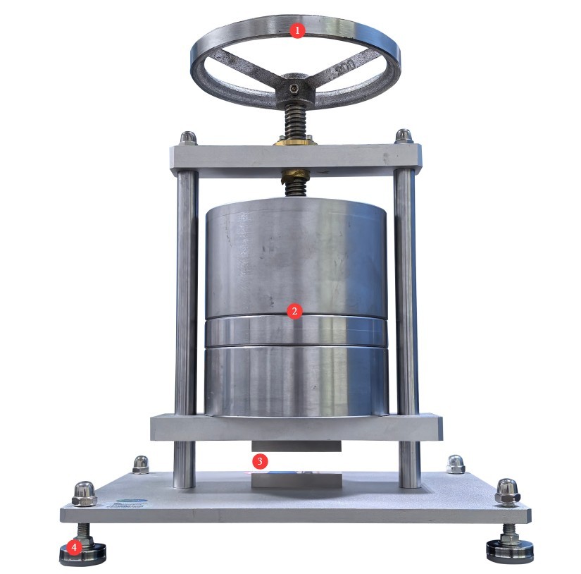
Figure 3-1
4. Compression Test Procedure
4.1 Pretreatment of Test Specimens
Samples with surface defects such as dents, cracks, or obvious deformation were excluded; none of the selected test specimens had undergone any destructive testing.
4.2 Test Conditions
| Standard Sections | Test Environment Temperature | Compression Force Value |
| GB/T 2099.1-2021, Clause 10.1 | 40±2°C | 150 N |
| IEC 60884-1:2022, Clause 10.2 | 35±2°C | |
| GB/T 2099.1-2021, Clause 24.6 | 23±2°C | 300 N |
| IEC 60884-1:2022, Clause 24.6 |
4.3 Test Procedure
4.3.1 Clause 10.1 of GB/T 2099.1-2021 / Clause 10.2 of IEC 60884-1:2022
The load shall be applied for 5 minutes; the specimen shall then be removed from the testing apparatus and inspected 15 minutes later. The specimen shall not deform to the extent that the dimensions specified in the relevant standard—which are intended to ensure safety—are unduly altered.
4.3.2 Clause 24.6 of GB/T 2099.1-2021 / Clause 24.6 of IEC 60884-1:2022
See Figure 4-1. First, place the specimen in the position shown in Figure 8a) (Figure 6a) in the IEC standard) and apply the force for 1 minute. Then, place the specimen in the position shown in Figure 8b) (Figure 6b) in the IEC standard) and subject it to the same force for another 1 minute.
Fifteen minutes after the specimen is removed from the testing apparatus, it shall show no damage within the scope defined by this standard.
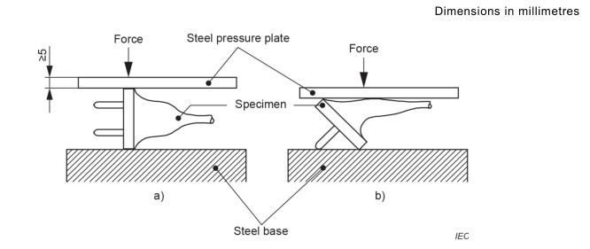
Figure 4-1
5. Post-Test Procedures
5.1 Device Reset
Turn the handwheel to lower the pressurized weight assembly to its lowest position to prevent the equipment from being subjected to prolonged loads when not in use.
5.2 Sample Preparation
Separate the samples that passed and failed the test, label them clearly, and avoid mixing them up.
5.3 Cleaning and Tidying Up the Test Site
Use a lint-free, soft cloth to wipe dust and debris from the handwheel, weights, and the surface of the device. Do not rinse the equipment directly with water.
Organize the tools and weights on the workbench, arrange them neatly, and clean up any debris left over from the experiment.
6. Routine Maintenance and Care
6.1 Regular Maintenance
Apply rust-preventive oil to the surface of the weights every three months to prevent rust; apply lubricating grease to moving parts such as brackets and handwheel shafts to prevent jamming during operation.
6.2 Calibration Interval Requirements
To ensure the accuracy and reliability of the device, it is recommended that it be sent periodically to a qualified third-party metrology laboratory for calibration. The recommended calibration interval is 12 months. Users may determine the specific calibration interval based on frequency of use, environmental conditions, and quality system requirements.
7. Troubleshooting and Resolving Common Problems
| Fault Symptoms | Possible Causes | Procedure |
| The stand moves jerkily when raising or lowering it | Dust buildup on the slide rails, insufficient lubrication, foreign objects lodged in the rails | Try again after removing dust from the slide rails, replenishing the lubricant, and clearing any foreign objects from the gaps. |
| Force Offset and Tilt | The device is not level, and the weights are not properly positioned. | Ensure the device is level; verify that all weights are properly positioned and not misaligned. |