
 English
 中文简体
中文简体 English
 Русский
 Español
 Português
 Türkçe
 العربية
 Deutsch
 Polski
 Italiano
 Français
 한국어
한국어 ไทย
ไทย Tiếng Việt
 日本語
日本語





























Oscillating Tube Water Spray Test System
User's Manual
Applicable LISUN models: JL-34、JL-34-OT-R1000、JL-34-OT-R1200、JL-34-OT-R1400、JL-34-OT-R1600、JL-34-OT-R200、JL-34-OT-R400、JL-34-OT-R600、JL-34-OT-R800、JL-34-R1000、JL-34-R1200、JL-34-R1400、JL-34-R1600、JL-34-R600、JL-34-R800、JL-34-TT-D1000KG50、JL-34-TT-D1200KG50、JL-34-TT-D1400KG50、JL-34-TT-D1600KG50、JL-34-TT-D200KG30、JL-34-TT-D400KG30、JL-34-TT-D600KG50、JL-34-TT-D800KG50
1. Unboxing and Basic Familiarization with the Equipment
1.1 Key Technical Specifications
| LISUN Model | Swing Arm Radius, Turntable Diameter/Maximum Load Capacity | IPX3, IPX4 | |||
| Test Host | Swing Pipe | Test Turntable | Number of holes N | Total water flow rate q | |
| N/A | JL-34-OT-R200 | JL-34-TT-D200KG30 | R=200, D=200 mm/30 kg | 8, 12 | 0.56, 0.84 L/min |
| JL-34-OT-R400 | JL-34-TT-D400KG30 | R=400, D=400 mm/30 kg | 16, 25 | 1.1, 1.8 L/min | |
| JL-34-R600 | JL-34-OT-R600 | JL-34-TT-D600KG50 | R=600, D=600 mm/50 kg | 25, 37 | 1.8, 2.6 L/min |
| JL-34-R800 | JL-34-OT-R800 | JL-34-TT-D800KG50 | R=800, D=800 mm/50 kg | 33, 50 | 2.3, 3.5 L/min |
| JL-34-R1000 | JL-34-OT-R1000 | JL-34-TT-D1000KG50 | R=1000, D=1000 mm/50 kg | 41, 62 | 2.9, 4.3 L/min |
| JL-34-R1200 | JL-34-OT-R1200 | JL-34-TT-D1200KG50 | R=1200, D=1200 mm/50 kg | 50, 75 | 3.5, 5.3 L/min |
| JL-34-R1400 | JL-34-OT-R1400 | JL-34-TT-D1400KG50 | R=1400, D=1400 mm/50 kg | 58, 87 | 4.1, 6.1 L/min |
| JL-34-R1600 | JL-34-OT-R1600 | JL-34-TT-D1600KG50 | R=1600, D=1600 mm/50 kg | 67100 | 4.7, 7 L/min |
The equipment complies with the test requirements for IPX3 and IPX4 specified in GB/T 4208-2017, Sections 14.2.3–14.2.4 and Figure 4.
1.2 Unboxing and Checking the Contents
1.2.1 Unpacking and Visual Inspection
When unpacking the device, handle it gently to avoid scratching the outer casing with sharp tools. After unboxing, first inspect the exterior of the device to ensure there is no visible deformation or dents, and that the buttons are not damaged or loose. If you notice any abnormalities with the device or its accessories, do not turn it on. Please contact us immediately.
1.2.2 Main Unit and Accessories
Main Components of the Equipment.
| No. | Note |
| ① | Freestanding cabinets, two in total |
| ② | Turntable |
| ③ | Swing pipe; a single set of equipment may include one or more swing pipes of different sizes. |
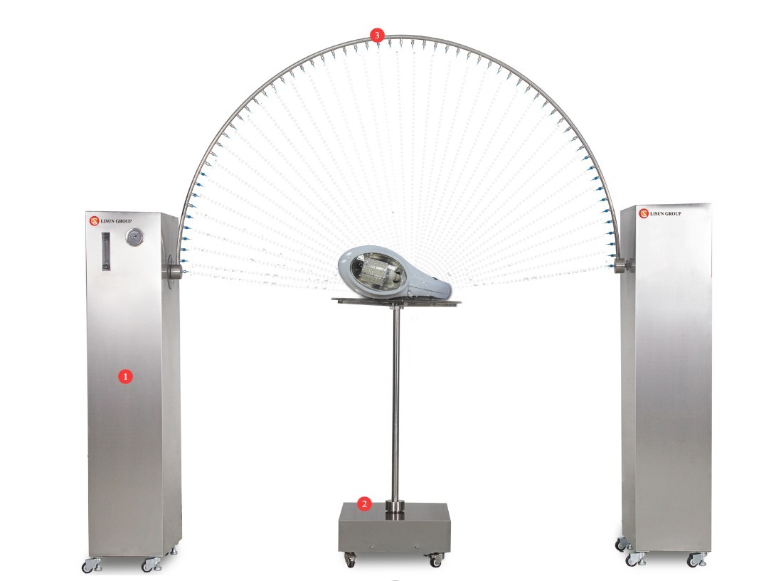
Figure 1
One of the freestanding cabinets contains a parts box filled with small parts, as shown in the figure below.
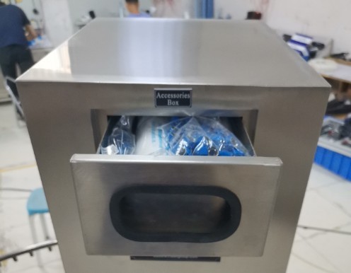
Figure 2
Other accessories are packaged separately; all major accessories are shown in the image below.
| No. | Note |
| ① Water pipe | Can be used to connect to the inlet, outlet, or overflow |
| ② Waterproof Plugs and Outlets | The sample used to connect the upright cabinet to the turntable during electrical testing |
| ③ Spare filter cartridge | The unit is already equipped with a filter cartridge; this is a spare. |
| ④ Strap | Can be used to secure samples to the turntable |
| ⑤ Spare plug | A sufficient number of plugs have already been installed on the swing pipe; these are spares. |
| ⑥ Hex socket screws | For use when installing the swing pipe |
| ⑦ Rubber gasket | |
| ⑧Needle Passing | If the needle becomes clogged, use this to clear it |
| ⑨Spare needles | Some needles are already attached to the needle holder; these are spares. |
| ⑩ Filter Wrench | Use when replacing the filter cartridge |
| ⑪Clamp | For securing water pipes |
| ⑫ Hex key | For use during equipment installation and commissioning |
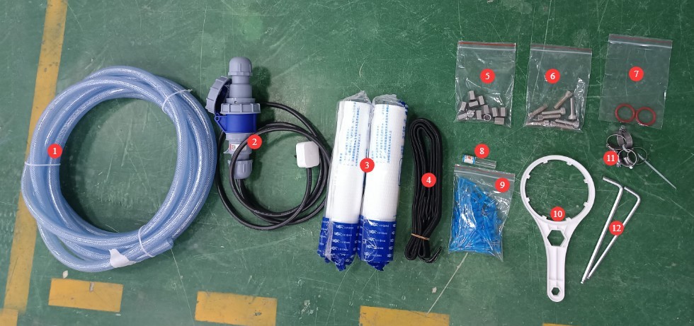
Figure 3
Download links for the digital user manual, software, warranty card, and other materials have been sent via email. Please download them promptly. If you missed the email, you may contact us directly to receive the download links again.
2. Safety Precautions
2.1 Electrical Safety
2.1.1 Power Connection Specifications
Based on the nameplate, connect the test chamber to the correct power source, typically 220 V, 50 Hz (60 Hz available upon request), and ensure the voltage and frequency are correct. Please use a dedicated circuit to avoid sharing the circuit with other high-power equipment. Verify that all connections are secure and free of looseness.
2.1.2 Grounding Requirements
The test chamber must be reliably grounded, with a grounding resistance of ≤4 Ω. It is prohibited to use gas pipes, non-metallic water pipes, or neutral wires as substitutes for the grounding wire. After grounding is complete, use the Grounding Resistance Tester to measure the ground resistance. Power may only be applied after confirming that the resistance meets the requirements, to prevent electric shock, test chamber malfunctions, or measurement errors caused by poor grounding.
2.1.3 Electrical Operating Contraindications
Before wiring, inspecting, or maintaining equipment, you must disconnect the main power supply and confirm that there is no residual voltage before proceeding;
Do not operate the test chamber’s power switch, touchscreen, or instrument buttons with wet hands to avoid the risk of electric shock;
Do not place any foreign objects (such as tools or paper) inside the electrical control cabinet to prevent dust or foreign objects from causing short circuits or damaging components;
Do not plug in or unplug power cords or signal cables while the equipment is running to prevent short circuits that could damage the controller or electrical components.
2.2 Operational Safety
When the swing tube is in operation, do not place any objects in the test area; personnel must stay well outside the swing tube’s range of motion, and must not extend their bodies or hands into the swing area; do not replace needles or plugs, or touch the swing tube, until it has come to a complete stop;
Before placing or removing a sample, ensure that the swing arm is reset to zero and the turntable has come to a complete stop; secure the sample exactly at the center of the turntable to prevent it from falling off while the turntable is rotating; the sample’s weight must not exceed the turntable’s load capacity to avoid damaging the turntable;
If the equipment malfunctions, non-professionals are prohibited from disassembling or repairing it; contact LISUN Customer Service or operate the equipment only under the guidance of a technician.
2.3 Environmental Safety
Sufficient clearance should be maintained between the wall and surrounding equipment (such as other test equipment and shelving) to allow for the swing of the test arm and to facilitate operation and maintenance;
Both cabinets must be placed on a sturdy, level surface. Use a level to ensure they are level, making sure the bubble in the level is centered. If the equipment is tilted, it may cause the swing arm to move unevenly or even damage the equipment. Note: The feet on both cabinets are adjustable to ensure they are level.
2.4 Other
For any matters not covered in this manual, please proceed with caution or contact us.
3. Equipment Overview and Assembly
3.1 Equipment Assembly
3.1.1 Positioning of the Vertical Cabinet and Turntable
Position and align the two cabinets according to the swing arm dimensions. Be sure to leave sufficient space between the cabinets and the wall to allow the swing arm to rotate. One of the cabinets is equipped with a touchscreen; be sure to leave enough space for operation. Place the turntable exactly in the center to prevent the swing arm from colliding with it during normal testing.
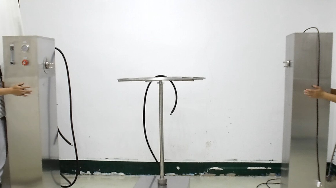
Figure 4
3.1.2 Swing Pipe Installation
Each of the two upright cabinets has a washer that needs to be inserted into the connection between the upright and the swivel tube.
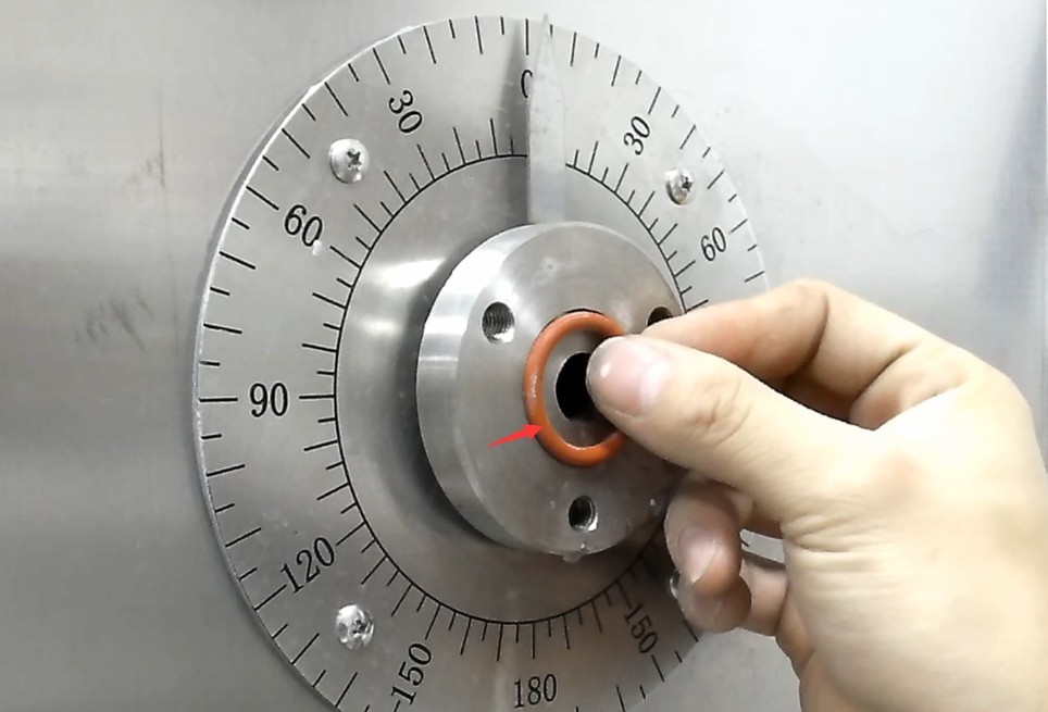
Figure 5
Remove the swing arm.
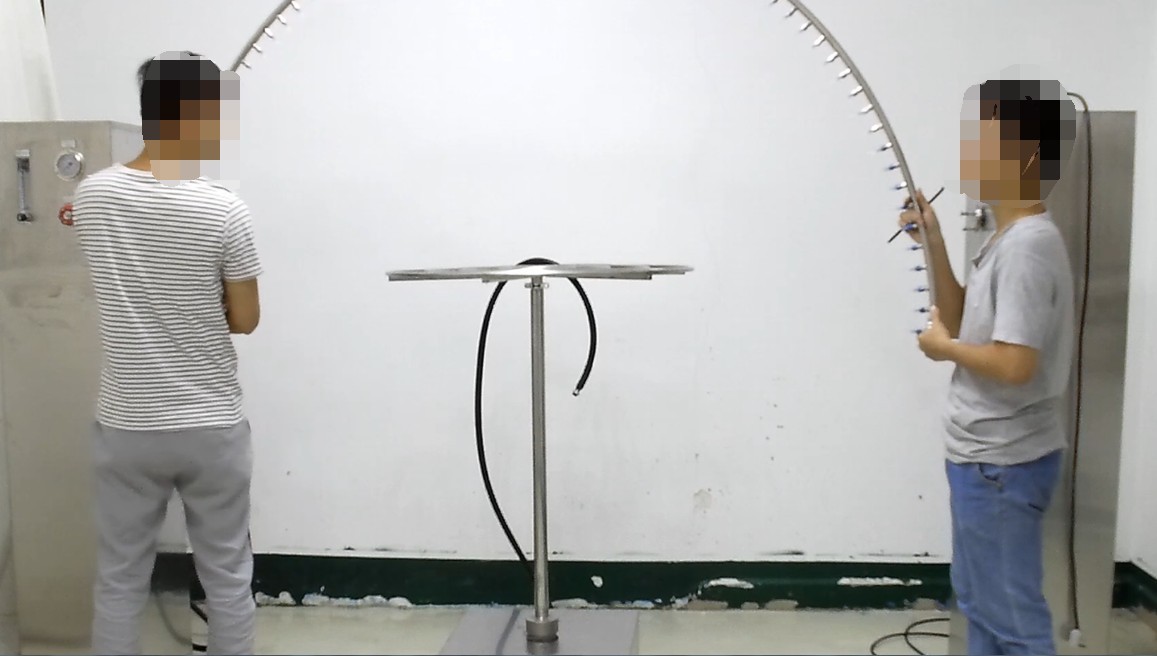
Figure 6
The swing pipe has an inlet at only one end.
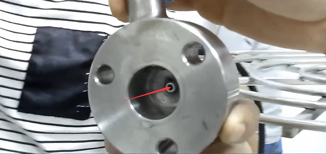
Figure 7
Of the two connections between the vertical cabinets and the swing pipe, only one has an outlet; connect the inlet end of the swing pipe to the outlet end of the vertical cabinet. Note: The direction of the swing pipe should match the direction of the pointer on the vertical cabinet’s angle dial.
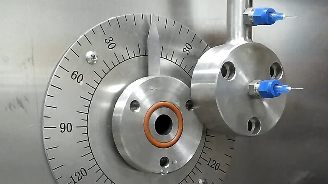
Figure 8
Tighten the three hex screws on each side.
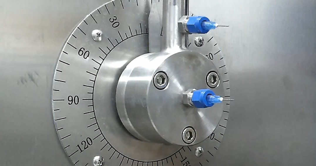
Figure 9
Readjust the position of the cabinet and screw the feet on the bottom of the cabinet securely in place. This will prevent the cabinet from sliding when the swing arm rotates.
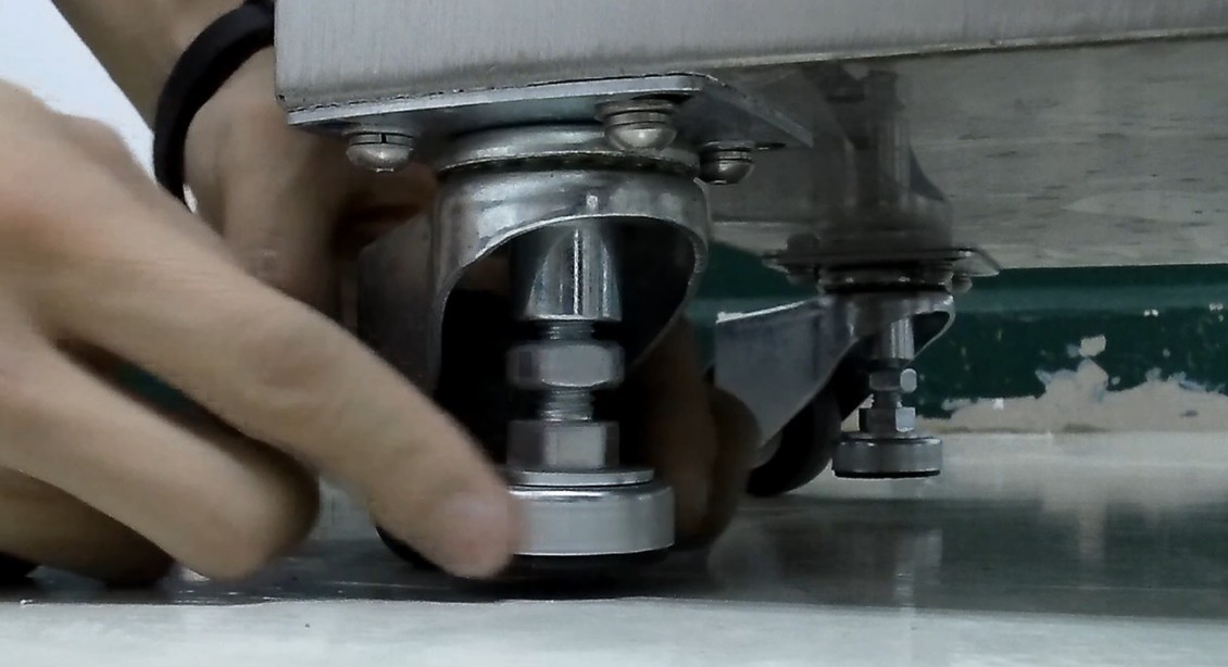
Figure 10
3.2 Cable Connections
| No. | Note |
| ① | Device power cord. Please connect it to the correct power source according to the device’s nameplate. |
| ② | Sample power cord—please connect it to an appropriate power source based on the item being tested. Note: Abnormal conditions, such as short circuits, may occur during testing; you may connect an external ground-fault circuit interrupter here. |
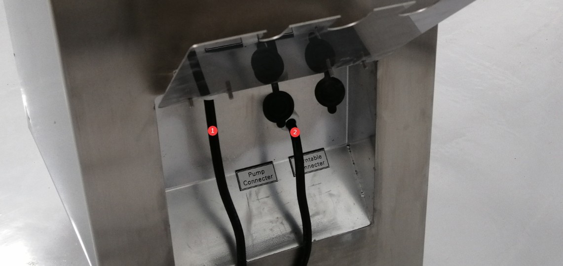
Figure 11
Another upright cabinet is connected to a water pump cable.
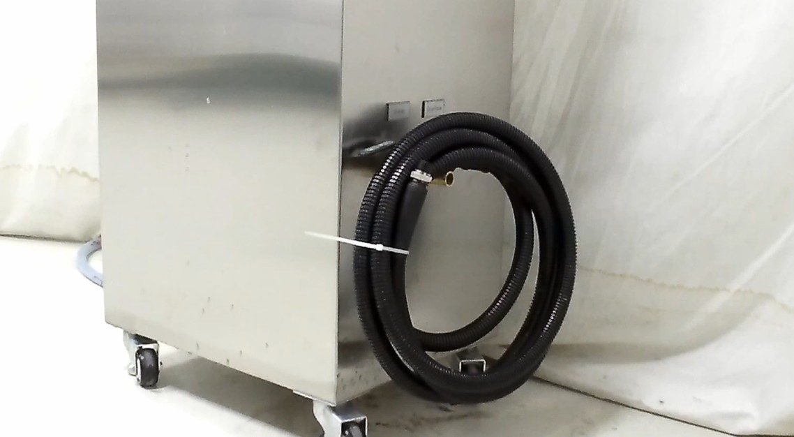
Figure 12
The turntable is connected to the motor cable.
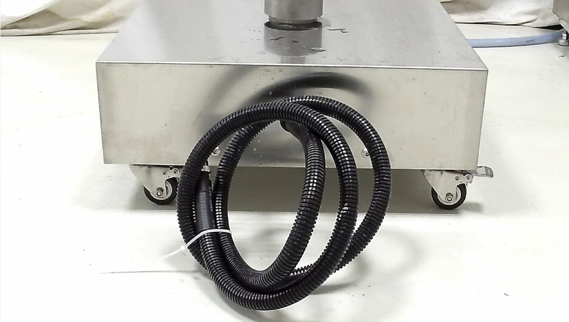
Figure 13
Please follow the link indicated.
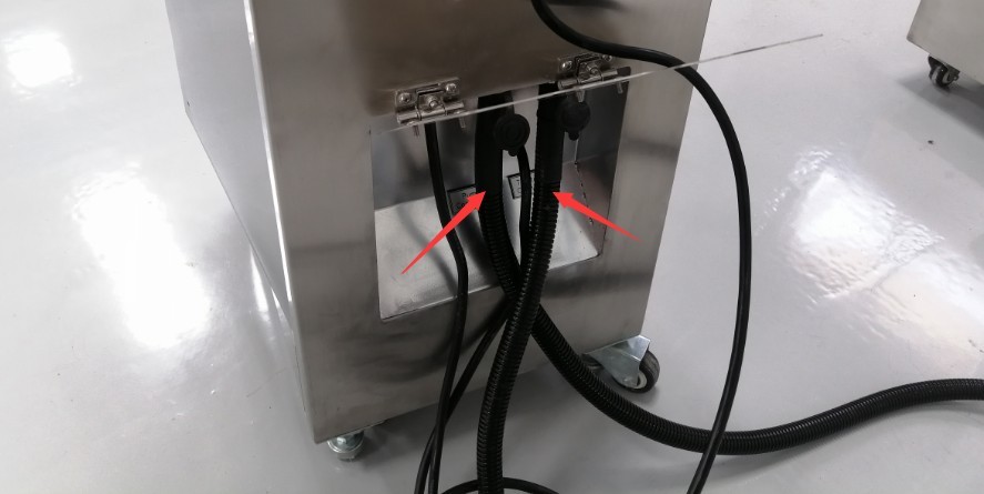
Figure 14
This is a waterproof plug provided by Li Shan.
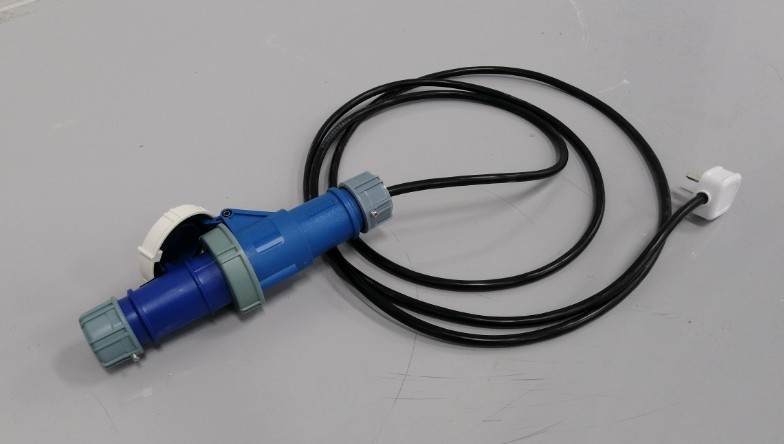
Figure 15
Plug one end into the outlet on the tall cabinet.
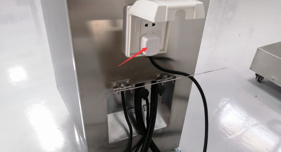
Figure 16
The other end is used to connect the sample. Note: The turntable automatically rotates forward and backward during the test to prevent the power cord from becoming tangled.
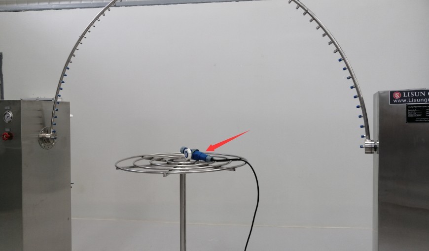
Figure 17
3.3 Water Tank Assembly
3.3.1 Water Pipe Connections
| No. | Note |
| ① Inlet | Under normal circumstances, the valve at the water inlet should remain open. There is a float valve inside the tank that automatically closes the water inlet once the tank is full. |
| ② Drain opening | Under normal circumstances, simply keep the valve closed. If the equipment will not be used for an extended period, or if you need to empty the tank, close the inlet valve and then open the drain valve. |
| ③ Overflow Outlet | Under normal circumstances, water should not overflow. If the float valve in the tank malfunctions and is unable to automatically regulate the water level, water may overflow from the overflow outlet. |
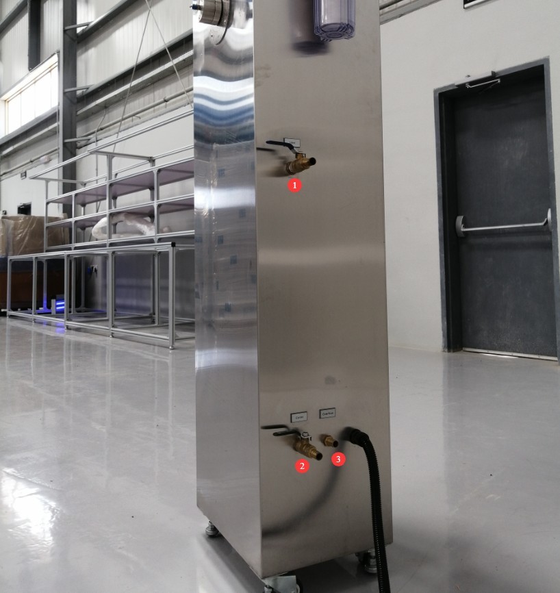
Figure 18
Note 1: Before using the device for the first time, please inspect the water tank and all water lines, remove any debris, and rinse with clean water.
Note 2: We recommend using deionized water or purified water (a water purifier may be used); if tap water is used, the minerals and impurities it contains can easily cause scale buildup, which affects the test water flow rate and may require frequent replacement of filter cartridges, unclogging of needles, cleaning of solenoid valves, and other maintenance—and may even damage the water pump.
3.3.2 Overview of the Water Tank’s Internal Structure
| No. | Note |
| ① Mechanical Float | A mechanical float is connected to the inlet. As the water level in the tank rises or falls, the mechanical float moves up or down, automatically controlling the opening and closing of the inlet. |
| ② Electronic Float | There are two in total. If the mechanical float fails and the water level continues to rise, causing the upper-level electronic float to rise, the touchscreen program will trigger an alarm; if there is a water shortage in the tank and the lower-level electronic float does not rise, the touchscreen program will trigger an alarm. |
| ③ Overflow Outlet | If the water level in the tank rises uncontrollably, it will flow out through the overflow outlet. |
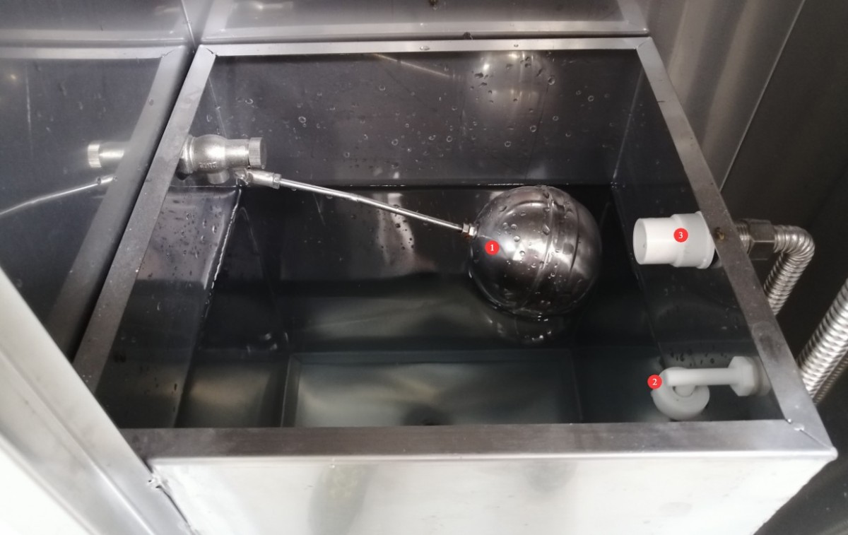
Figure 19
3.4 Powering On the Equipment
After verifying that all components are properly connected and that there are no abnormalities, turn on the device.
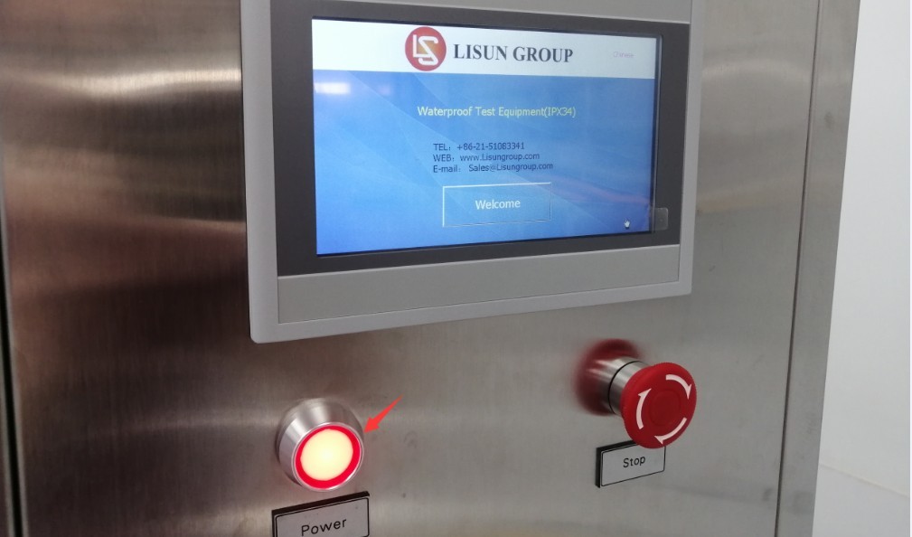
Figure 20
4. Introduction to the Touchscreen Program
4.1 Components of the Program’s Main Interface
4.1.1 User Interface
| No. | Note |
| ① Water resistance rating: IPX3 | Once selected, you can configure the IPX3 test parameters and perform the IPX3 swing-nozzle spray test. |
| ② Water resistance rating: IPX4 | Once selected, you can configure the IPX4 test parameters and perform the IPX4 swing-nozzle spray test. |
| ③ Sample Power Supply | The sample power can be turned on or off. When the sample power is turned on for testing, the program will automatically supply power to the sample according to the sample on/off times set in the parameter settings interface. |
| ④ Test Parameters | Click to access the test parameter settings screen |
| ⑤ Factory Settings | When the equipment is operating normally, there is no need to enter debug mode. If the equipment’s test parameters are abnormal, you may enter debug mode. A password is required; please contact us. |
| ⑥ Manual Window | Before the official test, you can check in the manual window to confirm that all device functions are working properly. |
| ⑦ Clear and Reset | Before starting a test, click here to clear the data from the previous test. |
| ⑧ Return the swing arm to zero | If the pendulum is not in the 0-degree position (directly above), click it to reset it to zero before the test. |
| ⑨ Start the Test | Click to start the swing-arm rain test |
| ⑩ Test stopped | Click to stop the swing-arm rain simulation test |
| ⑪ Test Duration Display | Display the current test duration |
| ⑫ Standard Flow Display | Displays the standard water flow rate required for the current swing arm size and waterproof rating |
| ⑬ Sample exposure time | Display the current power-on duration for the sample |
| ⑭ Power-off time for the sample | Display the duration of the power outage for the current sample |
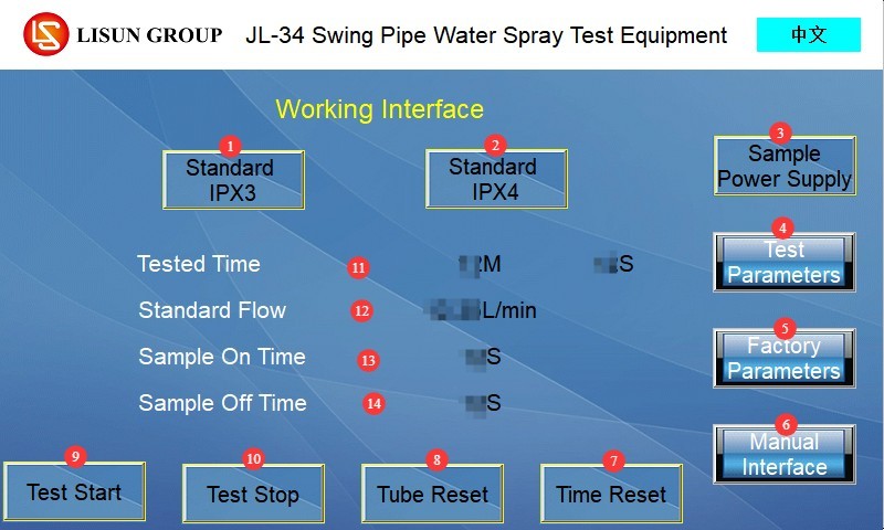
Figure 21
Note: If your equipment includes multiple swing pipes, you must select the size of the swing pipe currently in use on this screen.
4.1.2 Parameter Settings Interface
| No. | Note |
| ① Test Duration | The total test duration can be set; the GB/T 4208-2017 standard specifies that the test duration for both IPX3 and IPX4 is 10 minutes. |
| ② Swing Angle | The IPX3 standard is set at 120°, the IPX4 standard at 350°, with an upper limit of 350°. |
| ③ Turntable Speed | Unit: r/min; adjustable from 1 to 5 r/min; factory default is 1 r/min; no adjustment is required for standard testing. Note: During IPX3 testing, in accordance with the standard, the turntable will automatically rotate to two angles, and the test is conducted with the sample at rest; During IPX4 testing, the turntable rotates continuously at a speed of 1 r/min. For samples that require power during testing, the turntable automatically rotates in both clockwise and counterclockwise directions to prevent the sample’s power cord from becoming tangled. |
| ④ Time the sample is energized | Set the duration for which the sample remains energized during the test, in seconds |
| ⑤ Time the sample is de-energized | Set the duration of continuous power interruption for the sample during the test, in seconds |
| ⑥ Back | Click to return to the work interface |
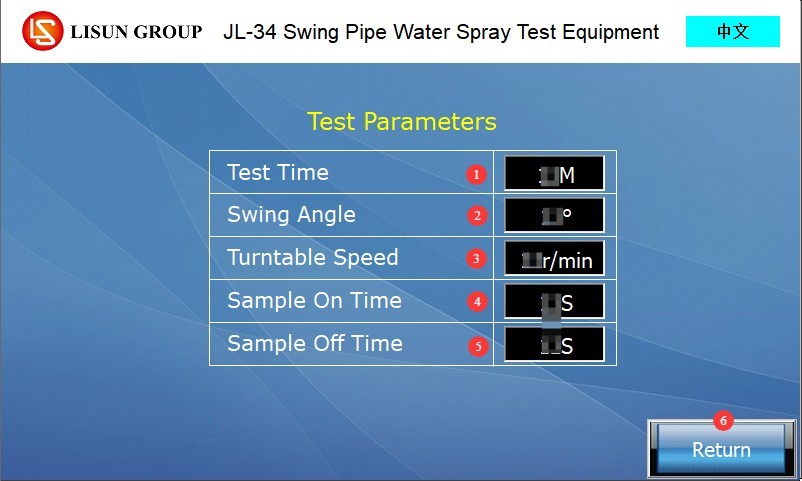
Figure 22
Note: Continuous power supply: Power-on time = test duration; power-off time = 0 s; No power supply: Power-on time = 0 s; power-off time = test duration.
4.1.3 Manual Window
| No. | Note |
| ① Pump Switch | The water pump can be turned on or off; once turned on, water begins to flow into the swivel pipe at the flow rate set by the flow meter. |
| ② Sample Power Supply | If the sample power supply and the sample are connected, you can turn the sample power supply on or off. |
| ③ Forward rotation of the swing pipe | Click to rotate the swing arm clockwise or counterclockwise; release to stop. Be careful not to let the swing arm collide with the turntable. |
| ④ Swing Arm Reversal | |
| ⑤ Turntable rotating clockwise | Click to rotate the turntable clockwise or counterclockwise; release to stop. Note: If there are wires between the turntable and the sample, do not rotate in one direction for an extended period to prevent the wires from becoming tangled. |
| ⑥ Turntable Reversal | |
| ⑦Back | Click to return to the work interface |
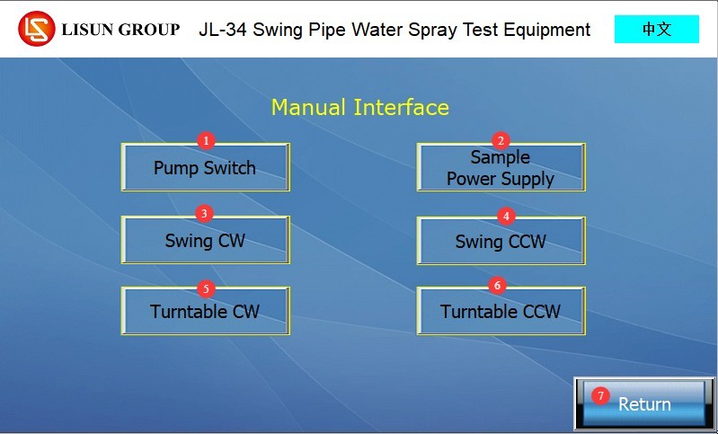
Figure 23
4.2 Description of the Program Alarm Interface
Emergency stop has not been reset. Please turn the emergency stop button clockwise to reset it, then try again.
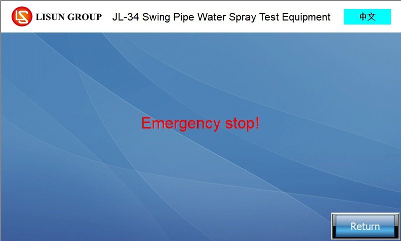
Figure 24
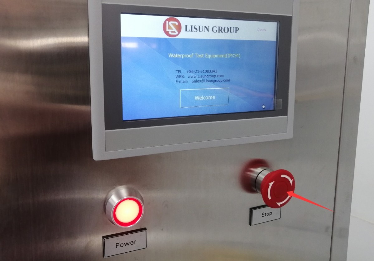
Figure 25
The swing-arm spray test is complete. Click “Back” to return.
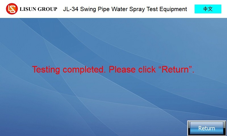
Figure 26
No water resistance rating has been selected. Please click “Back,” select the desired water resistance rating, and try again.
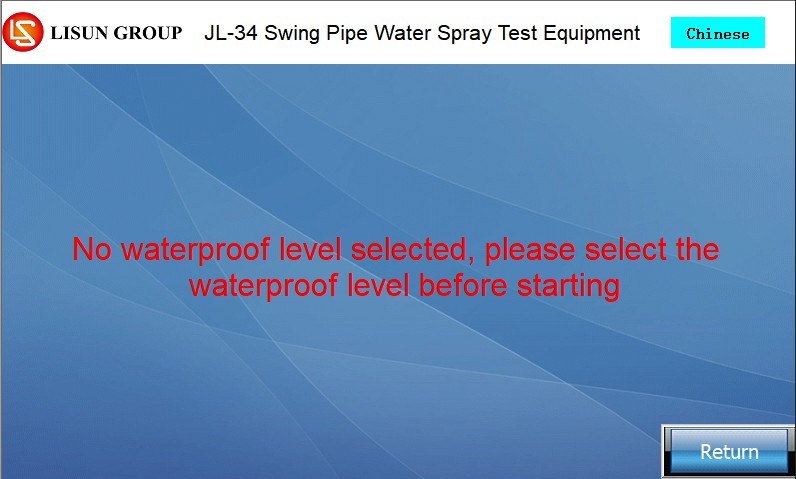
Figure 27
The test time has not been reset. Please click “Back,” then click “Reset” to clear the previous test data and try again.
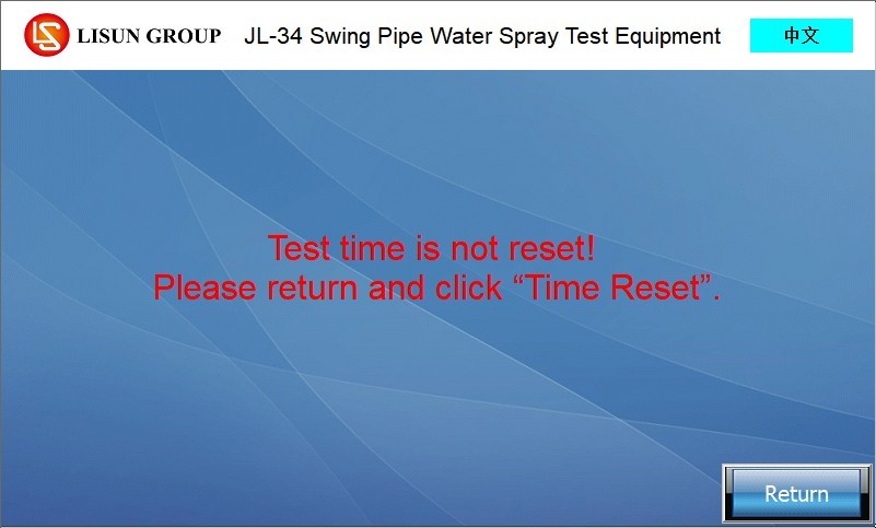
Figure 28
The swing arm has not been reset to zero. Please click “Back,” then click “Reset Swing Arm” to rotate the swing arm to the 0-degree position, and try again.
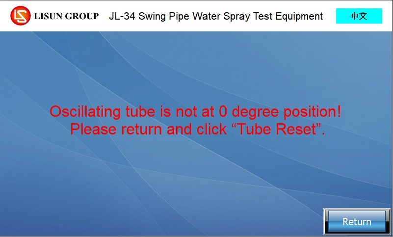
Figure 29
The water tank is overfilled. Refer to Section 3.3.2 to verify that the mechanical float is functioning properly, reset it, and lower the water level in the tank below the electronic float. Alternatively, check whether the upper-level electronic float is stuck; if it is jammed by debris, remove the debris and lower the float.
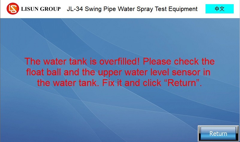
Figure 30
The water tank is low on water. Refer to Section 3.3.2 to verify that the water level in the tank is normal. Alternatively, check to see if the electronic float switch is stuck; if it is stuck due to debris, remove the debris and allow the float to rise. Tap “Back” to clear the alarm.
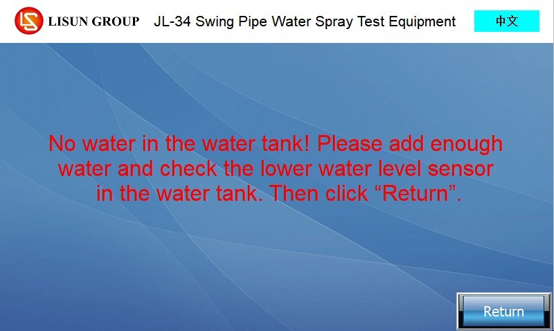
Figure 31
5. Preparations Before the Test
5.1 Sample Installation
5.1.1 Preliminary Inspection of Samples
Inspect the sample to ensure it is in good condition, with no damage or deformation; verify the test requirements for the sample (whether power-on testing is required, and the water resistance rating); if power-on testing is required, refer to Section 3.2 to connect the sample’s power cord to an appropriate power source.
5.1.2 Sample Mounting and Positioning
Place the sample exactly in the center of the turntable and secure it firmly with a tie-down strap to prevent it from shifting or falling off while the turntable is rotating;
If the sample has any protruding parts, ensure that they will not collide with the swing arm to prevent damage to the equipment and the sample;
For electrical testing, follow the instructions in Section 3.2 to connect the sample using a waterproof plug, socket, and power cord. Check that the connection is secure, with no loose connections or short circuits, and verify that all connections in the circuit are properly sealed against water.
5.2 Matching and Commissioning of the Swivel Tube and Turntable
5.2.1 Calibration of the IPX3 Test Swing Arm
According to the requirements of GB/T 4208-2017, Section 14.2.3, IPX3 involves water spray within 60° arc segments on either side of the swing tube’s midpoint. The nozzles in the non-60° arc segments of the swing tube must be sealed with plugs, leaving only the nozzles within the 60° arc segments on either side of the midpoint (a total of 120° arc segment). Ensure that the seals are secure and free of leaks.
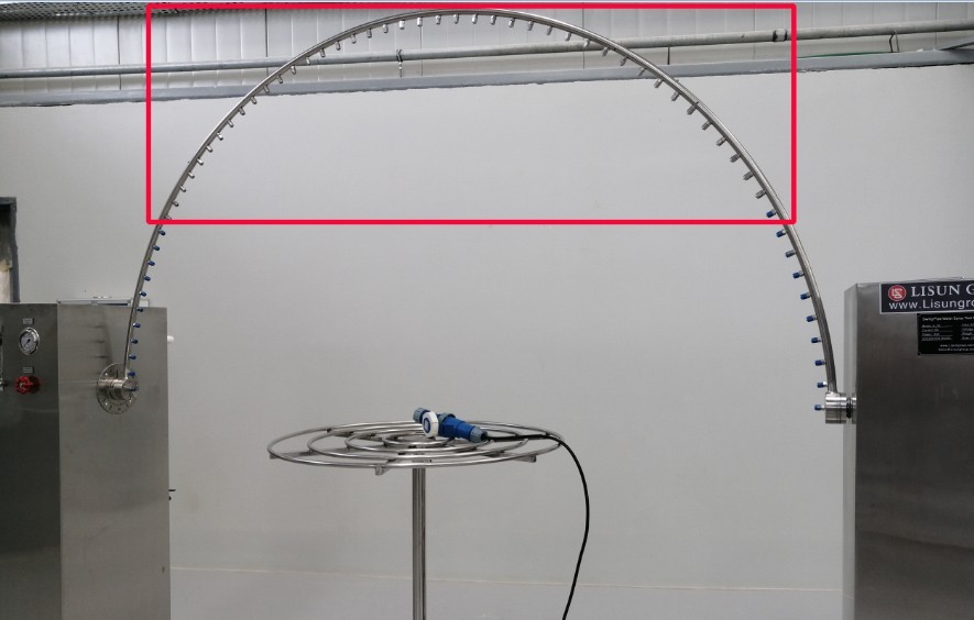
Figure 32
5.2.2 Calibration of the IPX4 Test Swing Arm
According to the requirements of GB/T 4208-2017 Section 14.2.4, the IPX4 test involves water spray within 180° arc segments on either side of the swing tube’s midpoint (approximately 360°). All plugs on the swing tube must be removed and replaced with nozzles; check that the nozzles are functioning properly andand ensure they are not clogged or loose.
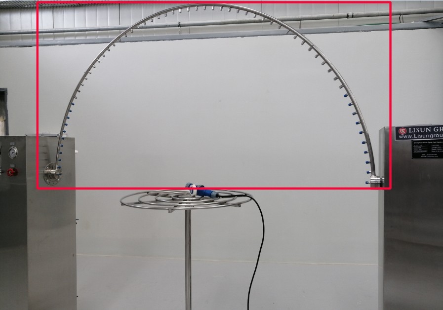
Figure 33
5.2.3 Turntable Height Adjustment
Manually adjust the turntable height according to the sample size so that the distance between the sample and the nearest point to the swing tube nozzle is ≤200 mm (in accordance with the requirements of Figure 4 in GB/T 4208-2017). After adjustment, lock the turntable height in place to prevent any height deviation during the test.
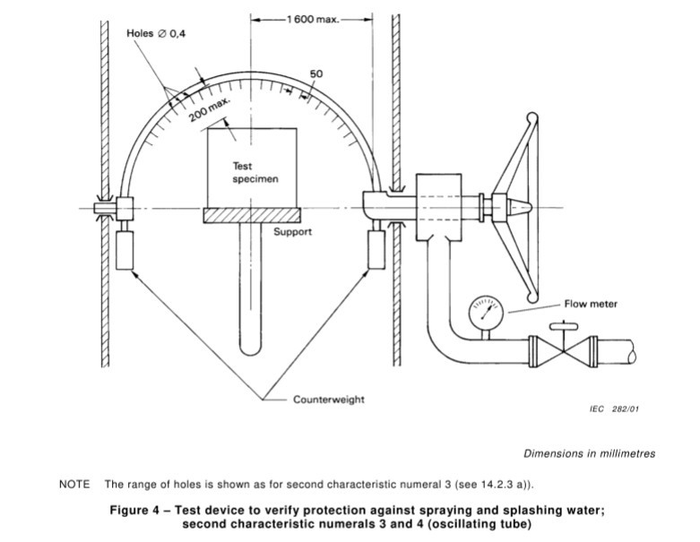
Figure 34
Note: Depending on the size of the sample, you may need to use different sizes of swing arms and turntables.
5.3 Pre-commissioning of Equipment
5.3.1 Equipment Functionality Check
If the equipment has not been used for an extended period, or if you need to verify in advance that all its functions are still operating normally, refer to Section 4.1.3 to check and confirm that the equipment’s pump, turntable, and swing pipe are functioning properly.
5.3.2 Needle Inspection and Flow Rate Pre-adjustment
Still referring to 4.1.3, turn on the water pump.
| No. | Note |
| ① Flow Meter Adjustment | Adjust the water flow rate (L/min) to meet the standard requirements. Refer to Section 4.1.1; the working interface displays the standard water flow rate for the current settings, or you can refer to the water flow rate required for the standard calculation. |
| ② Water Pressure Adjustment | Standard specifications do not specify any water pressure requirements, so no adjustment is necessary. If specific standards require a certain water pressure, you can adjust it by turning this valve. |
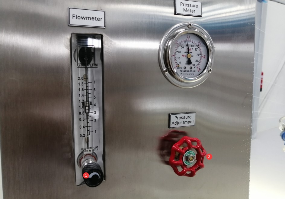
Figure 35
Note: Please ensure that water flows evenly from all nozzles. If any nozzles are clogged, you may not be able to adjust the water flow rate to meet the required standards. Use a nozzle cleaner to clear all nozzles, reinstall them, and then continue adjusting the water flow rate until it meets the standards.
Once commissioning is complete, you can turn off the pump.
6. Swivel-nozzle rain test
6.1 Start-up Test
On the touchscreen program interface, select the required waterproof rating. If the sample is powered, click “Sample Power,” then click “Clear and Reset” and “Pendulum Zero,” and finally click “Start Test” to begin the pendulum rain test.
6.2 The test is conducted automatically according to the standard settings.
6.2.1 IPX3 Oscillating Nozzle Rain Test
The pump starts, and the swing arm oscillates at a cycle of 120°/4 seconds. After 5 minutes of testing, the turntable automatically rotates the sample 90° horizontally, followed by another 5 minutes of testing. The total test duration is 10 minutes.
6.2.2 IPX4 Swivel Nozzle Rain Test
The pump starts, the swing arm oscillates at a rate of 350° per 12 seconds, and the turntable rotates at a constant speed of 1 r/min; the test continues for 10 minutes. The sample support has no water barrier, and the sample is exposed to water splashes from all directions.
6.3 Real-Time Monitoring of Tests
6.3.1 Water Spray from the Needle and Water Flow Rate
All nozzles delivered water evenly throughout the test, with no blockages. If the flow rate fluctuates during the test, the flow meter can be fine-tuned to keep the water flow rate stable at the standard rate.
6.3.2 Electrical Conditions of the Sample
Power to the sample is automatically turned on and off according to the set schedule. If an abnormality occurs during the test—such as a short circuit—the test can be stopped immediately; after inspecting the sample, the test can be repeated.
6.3.3 Other Exceptions
The swing angle of the swing arm is normal, with no jamming or unusual noises; the turntable rotates smoothly; the sample does not shift; and the program does not trigger any alarms. If any abnormalities occur, stop the test immediately, troubleshoot the issue, and then restart the test.
7. Post-Test Procedures
7.1 Immediate Actions Upon Test Completion
7.1.1 Remove the sample
Press the “Stop Test” button, or wait for the test to end automatically. The swing arm will automatically return to the 0-degree position, the turntable will stop rotating, and power to the specimen will be cut off (for specimens undergoing powered testing). Remove the specimen from the turntable.
7.1.2 Touchscreen
Check whether the test time display on the interface is working properly, then click “Clear and Reset” to prepare for the next test.
7.2 Shutdown
After all tests for the day are completed, turn off the water supply valve and switch off the power to the equipment.
7.3 Evaluation of Test Results
Use a dry cloth to wipe away any water stains from the sample’s outer surface, and then test the sample. Determine whether the sample passes the test based on the following criteria.
| Evaluation Criteria | Specific Requirements |
| Safety | Insufficient water supply does not affect the normal operation of the equipment or compromise safety. |
| Insulation Protection | Water does not accumulate on insulated components where it could cause tracking along the creepage distance. |
| Protection of Electrical Components | Water must not enter live parts or windings that are not designed to operate in damp conditions. |
| Cable Protection | Water does not accumulate near the cable terminations or enter the cable |
| Effectiveness of Drain Holes | If there are drain holes, it must be verified that incoming water will not accumulate and that it can drain away without damaging the equipment. |
| Equipment without drain holes | If water accumulates and endangers live parts, follow the acceptance criteria specified in the relevant product standards. |
8. Daily Maintenance and Care of Equipment
8.1 Daily Cleaning
Wipe water spots and dust from the surface of the equipment, paying special attention to cleaning the turntable and swing arm areas to prevent water spots from forming limescale;
Wipe the touchscreen and control panel with a dry cloth to prevent water and dust from entering the internal circuitry;
Thoroughly clean the water tank at least once a week: Drain any standing water, then wipe it dry with a clean cloth. After cleaning, check the inner walls of the tank for rust or scale buildup. If there is minor rust, gently wipe it with a rust remover, then rinse thoroughly with clean water.
8.2 Regular Inspections and Replacements
Needle: Check that the needle on the oscillating tube is not clogged, loose, or deformed, and verify that the water drips evenly. If the needle is clogged, use a needle cleaner to clear the blockage.
Connections: Check all connections on the swing pipe, water lines, and electrical circuits to ensure there are no leaks or loose connections.
Filter Cartridge: Inspect the filter cartridge inside the filter. If the cartridge has turned brown (indicating it is saturated with adsorbed impurities), replace it with a new one immediately.
8.3 Maintenance of Idle Equipment
8.3.1 Short-term Idle (within 1 month)
Drain all standing water from the water tank and water lines to prevent scale buildup on the needles and tubing;
Cover the entire unit with a dust-proof cloth to prevent dust from entering;
Keep the equipment in a dry, well-ventilated area.
8.3.2 Long-term inactivity (more than 1 month)
Complete all maintenance tasks for equipment that will be idle for a short period; disconnect all electrical and water connections from the equipment; remove the water hoses, let them air dry, and store them properly;
Apply a layer of rust-preventative oil to the inner walls of the water tank and the surfaces of metal parts to prevent rust; store the equipment in a cool, dry place away from direct sunlight;
Apply a small amount of industrial lubricant to moving parts, such as turntable bearings, to prevent rust and seizing;
The equipment should be powered on once a month. Switch to the manual screen to test all functions, then shut it down after 5 to 10 minutes of operation to prevent circuit deterioration.
9. Troubleshooting and Resolving Common Issues
| Fault Symptoms | Possible Causes | Procedure |
| Touchscreen Alarm | See 4.2 | |
| The touchscreen is lit, but the buttons do not respond when tapped | Touchscreen freezes, stains or water marks on the surface, internal touch module malfunction | Turn off the device, wait 5 minutes, and then restart it; wipe the touchscreen with a dry cloth to remove stains or water marks; if it still does not respond, contact us for repair. |
| The water flow from the needle is uneven. | Tilted cabinet, clogged needle, insufficient water flow | Use a level to ensure the cabinet is vertical and not tilted; use a drain snake to clear any clogs in the drain line; ensure that the water flow meets the specified requirements. |
| The water flow is insufficient and cannot be increased. | Clogged needle, clogged filter cartridge, clogged water pump | Use a cleaning needle to unclog the nozzle that isn’t dispensing water; replace the filter cartridge; disassemble the water pump, clean out the internal debris, and reassemble it. |