
 English
 中文简体
中文简体 English
 Русский
 Español
 Português
 Türkçe
 العربية
 Deutsch
 Polski
 Italiano
 Français
 한국어
한국어 ไทย
ไทย Tiếng Việt
 日本語
日本語





























Spraying Nozzle And Splashing Water Hand Held Test Device
User's Manual
Applicable LISUN models: JL-34S
1. Unboxing and Basic Familiarization with the Equipment
1.1 Key Technical Specifications
| Parameters | Note |
| Material | Nozzle: Brass; Movable baffle: Aluminum |
| Pore size | 0.5 mm |
| Number of holes | 1 (1 hole in the center) + 12 (12 holes in each of the 2 inner rings) × 2 + 24 (24 holes in each of the 4 outer rings) × 4, for a total of 121 holes |
| Nozzle Arc Radius | 75.5 mm |
| Movable Baffle | Can block spray holes within a 30° range of the nozzle; used when testing for IPX3 compliance |
| Inlet Pipe Diameter | 15 mm |
Fully complies with the test requirements for IPX3 and IPX4 specified in sections 14.2.3–14.2.4, clause (b), and Figure 5 of GB/T 4208-2017.
1.2 Unboxing and Inspection, and Introduction to the Equipment
1.2.1 Unboxing and Inspection
When unpacking the device, handle it gently to avoid scratching the exterior with sharp tools. After unboxing, first inspect the exterior of the device to ensure there are no visible deformities, dents, or other damage. If you notice any abnormalities with the device or its accessories, please contact us immediately.
1.2.2 Equipment Overview
| No. | Note |
| ① Inlet | Connect to a water source with sufficient water pressure using a water hose with an inner diameter of 15 mm. |
| ② Valves | Adjust the water flow to control the test water pressure. Note: The valve is fully closed when the handle is perpendicular to the water pipe, and fully open when the handle is parallel to the water pipe. |
| ③ Electronic Flow Meter | Display real-time water flow and determine whether the flow rate meets the standard |
| ④ Pressure Gauge | Displays real-time water pressure and determines whether it meets the standard |
| ⑤ Movable Baffle | Switch between IPX3 and IPX4 modes to control the spray angle range |
| ⑥ Nozzle | Standard nozzle layout, in compliance with standards |
| ⑦Balance weight | Assists in positioning the baffle to maintain a stable IPX3 water spray angle |
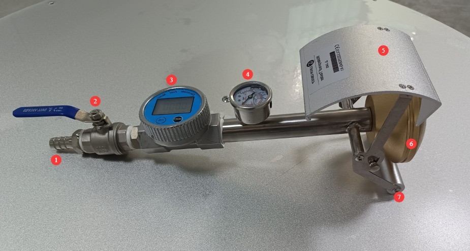
Figure 1
Links to download the electronic user manual, warranty card, and other materials have been sent via email. Please download them as soon as possible. If you missed the email, please feel free to contact us to request the download links again.
2. Safety Precautions
2.1 Electrical Safety
Do not place electrical outlets, power sources, or live equipment in the test area to prevent electric shock caused by water spray;
Before testing live samples, verify that insulation protection meets the required standards; do not connect directly to a power source for testing.
2.2 Operational Safety
2.2.1 Safety of Water Line Connections
Water pipes, inlets, and faucets must be securely tightened to prevent them from coming loose and leaking when water starts flowing.
2.2.2 Safety Precautions for Nozzle Operation
During testing, do not position your face, hands, or other body parts directly in the path of the water jet to avoid injury from the high-pressure water stream.
2.3 Sample Safety
The test specimen must be placed steadily and securely fastened to prevent it from tipping over or shifting during the test, which would invalidate the results.
3. Preparations Before the Test
3.1 Environmental Conditions and Sample Preparation
3.1.1 Test Environment Requirements
The test bench surface must be level, sturdy, and equipped with drainage; the environment must be free of strong winds and contaminants to avoid affecting the water spray performance.
3.1.2 Sample Pretreatment
A visual inspection of the sample revealed no damage, and the seals were intact; the sample was placed in its actual operating condition, with all removable parts remaining installed.
3.2 Pre-adjustment of Water Flow and Water Pressure
3.2.1 Water Supply Connection
Take a 15-mm-ID ribbed water tube, connect one end to the equipment’s water inlet, and tighten it securely; connect the other end of the tube to a clean tap, ensuring the connection is secure and free of any looseness.
3.2.2 Pre-adjustment
Open the unit’s inlet valve; the water flow rate indicated by the unit’s electronic flowmeter must reach (10±0.5) L/min, and the unit’s pressure gauge reading must be within the range of 50 kPa to 150 kPa (the unit’s pressure gauge is calibrated in MPa, i.e., 0.05 MPa to 0.15 MPa).
3.3 Confirmation of Test Mode
3.3.1 IPX3 Mode Verification
Move the adjustable baffle toward the nozzle and secure it, adjusting the spray angle to ±60°.
3.3.2 IPX4 Mode Verification
The movable baffle is moved away from the nozzle and secured in place, allowing water to spray in all directions (±180°).
4. Rain and Splash Resistance Test
4.1 IPX3 Water Splash Test (GB/T 4208-2017 14.2.3b)
4.1.1 Sample Placement and Alignment
Place the sample gently in the center of the test bench and secure it firmly so that it does not wobble.
4.1.2 Nozzle Position Adjustment
Hold the spray nozzle and adjust the distance from the sample to between 300 mm and 500 mm, aiming the nozzle at the sample from top to bottom.
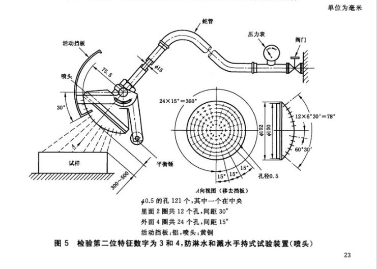
Figure 2
4.1.3 Timed Test
Start the timer once the water pressure and flow rate have stabilized. Test duration: 1 minute per square meter (based on the surface area of the sample housing, excluding the mounting surface), with a minimum of 5 minutes.
Maintain a constant water pressure and keep the nozzle angle unchanged during the test.
4.2 IPX4 Splash Protection Test (GB/T 4208-2017 14.2.4)
4.2.1 Sample Placement and Alignment
As in 4.1.1, the specimen is securely fastened to the test bench.
4.2.2 Nozzle Position Adjustment
As in 4.1.2, the distance between the nozzle and the sample should be 300 mm to 500 mm.
4.2.3 Timed Tests
Start timing once the water pressure has stabilized; the time requirement is the same as for IPX3. Slowly move the spray nozzle to ensure that the test specimen is exposed to water splashes from all directions.
The timer has stopped; the IPX4 test is complete.
5. Post-Test Procedures
5.1 Stopping the Test Process
5.1.1 Turn Off the Water Supply
Slowly close the water supply faucet to cut off the water supply to the appliance.
5.1.2 Pressure Relief and Drainage
Keep the equipment’s water inlet valve open, drain any remaining water from the sprinkler heads and water pipes, and relieve the pressure in the water system.
5.2 Site Cleanup
Wipe up water stains from the test bench and equipment surfaces, and remove standing water from the test area to keep it dry and clean.
5.3 Evaluation of Test Results
Use a dry cloth to wipe away any water stains from the outer surface of the sample, then test the sample. Determine whether the sample has passed the test based on the following criteria.
| Evaluation Criteria | Specific Requirements |
| Safety | Insufficient water supply does not affect the normal operation of the equipment or compromise safety. |
| Insulation Protection | Water does not accumulate on insulated components where it could cause tracking along the creepage distance. |
| Protection of Electrical Components | Water must not enter live parts or windings that are not designed to operate in damp conditions. |
| Cable Protection | Water does not accumulate near the cable terminations or enter the cable |
| Effectiveness of Drainage Holes | If there are drain holes, it must be verified that incoming water will not accumulate and that it can drain away without damaging the equipment. |
| Equipment without a drain hole | If water accumulates and endangers live parts, follow the acceptance criteria specified in the relevant product standards. |
6. Daily Maintenance and Care of Equipment
6.1 Maintenance After a Single Test
Drain any water accumulated inside the nozzle to prevent scale buildup, and wipe off any water from the surface of the equipment to keep it dry.
6.2 Regular Cleaning and Maintenance
Frequent use: Remove the curved panel from the nozzle once a week and wipe away any dirt inside;
Nozzle Orifice Blockage: After removing the curved surface of the nozzle, use a cleaning pin with a diameter of 0.4 mm or less to clear the blockage from the inside out. Do not use hard objects that could damage the nozzle orifice;
Lubricate moving screws and ball valves regularly to ensure smooth operation.
6.3 Long-Term Storage and Maintenance
Completely drain any water from the equipment and store it after it has dried; wrap glass pressure gauges in soft film to protect them from impact; store them in a dry, well-ventilated, and non-corrosive environment.
7. Troubleshooting and Resolving Common Problems
| Fault Symptoms | Possible Causes | Procedure |
| Nozzle Clogging | The water source contains impurities | Please refer to Section 6.2 to unclog the spray holes, remove any debris from the nozzles, and then replace the water source with clean water before retesting. |
| Water flow does not meet standards | Insufficient water pressure; some nozzles are clogged | Increase the inlet water pressure; if the nozzle is clogged, increasing the water pressure will not increase the water flow. Refer to Section 6.2 to unclog the nozzle before trying again. |
| There are fluctuations in water flow and water pressure | Unstable water pressure and loose pipe connections | Please try again after the water pressure has stabilized; please try again after tightening all water pipe connections securely. |