
 English
 中文简体
中文简体 English
 Русский
 Español
 Português
 Türkçe
 العربية
 Deutsch
 Polski
 Italiano
 Français
 한국어
한국어 ไทย
ไทย Tiếng Việt
 日本語
日本語





























UL Water Spray Test Device
User's Manual
Applicable LISUN models: JL-UL
1. Unboxing and Basic Familiarization with the Equipment
1.1 Key Technical Specifications
| Parameters | Note |
| External Dimensions of the Equipment | Approximately 1700 mm × 920 mm × 2150 mm |
| Adjustable Height Range of the Rain Shower Nozzle | Approximately 1000–2000 mm |
| Number of UL Nozzles | A total of 4 (3 installed on the elevating rain test apparatus; 1 installed on the spray test apparatus) |
| Distance from the ground to the water jet convergence point | 0–1000 mm |
| Sprinkler Spray Angle at Ground Level | Sprays water at a 45° angle upward and horizontally |
| Number of Pressure Gauges | 5 in total (each nozzle is equipped with one pressure gauge; the adjustable bracket is equipped with one additional master pressure gauge) |
The JL-UL Water Spray Test Device is designed in accordance with the requirements of Figure 38.1 andFigure 38.2, as well as the provisions of Figures 10 and 11 in the ANSI Z21.10.3-2004 and ANSI Z21.58 standards, and the CSA 4.3-2004 standard. It complies with UL 1598, UL 153, UL 154B, UL 1703, UL 8750, UL 1741, UL 514B, UL 1278, and UL 1571.
1.2 Unboxing and Checking the Contents
1.2.1 Unpacking and Visual Inspection
When unpacking the device, handle it gently to avoid scratching the casing with sharp tools. After unpacking, first inspect the exterior of the device to ensure there is no visible deformation or dents, and that the buttons are not damaged or loose. If you notice any abnormalities with the device or its accessories, please contact us immediately.
1.2.2 Main Unit and Accessories
| No. | Note |
| ① | Elevating Rain Test Apparatus |
| ② | Sprinkler Test System |
| ③ | Corrugated tubing, used to connect the water inlet |
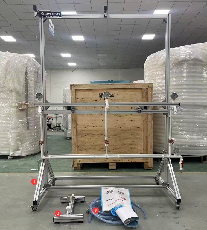
Figure 1
Download links for the electronic user manual, software, warranty card, and other materials have been sent via email. Please download them as soon as possible. If you missed the email, you may contact us to request the download links again.
2. Precautions for Use
2.1 Pre-Operation Safety Guidelines
2.1.1 Personnel Requirements
Operators must read this manual and familiarize themselves with the basic operating procedures. Unauthorized personnel are prohibited from operating the equipment. When operating the equipment, wear non-slip shoes and waterproof gloves to prevent water from splashing onto electrical equipment or any part of the body.
2.1.2 Site Safety
The test site must have sufficient operating space (no obstacles within 1.5 meters of the equipment), a waterproof floor, and drainage facilities; use of the equipment is prohibited in environments containing flammable, explosive, or corrosive liquids.
The adjustable rain test apparatus must be placed on a hard, level surface; it must not be tilted, and the casters must not be off the ground.
2.2 Inlet Connection
The adjustable rain simulation test apparatus and the water spray test apparatus are two separate systems designed for different tests; they must be connected to separate water supply faucets and cannot be used together.
We recommend using a pure water generator with sufficient water pressure. Refer to Section 4.1 or other relevant standards to determine the required water pressure.
2.3 Safety Guidelines for Operation
2.3.1 Water Pressure Regulation Requirements
When adjusting the water pressure, rotate the pressure调节 valve slowly. Do not turn it quickly or forcefully, as this can cause a sudden pressure surge and damage the pressure gauge or water pipes. If you notice bulging in the water pipes or leaks from the nozzles during the test, immediately shut off the water supply and stop the test.
2.3.2 Prohibition of Improper Operations
During testing, do not touch the nozzle outlet with your hands to avoid injury from the high-pressure water jet; do not disassemble equipment components or alter pipe connections without authorization; and do not move the equipment frame while the equipment is in operation.
2.4 Exception Handling
If a malfunction occurs during operation (such as a water leak, a sudden drop in pressure, the equipment shifting or tipping over, or abnormal water flow from the nozzle), immediately turn off the water supply valve. Do not use the equipment until the problem has been resolved. Never operate the equipment while it is malfunctioning.
3. Equipment Overview
3.1 Elevating Rain Simulation Test System
| No. | Note |
| ① | Inlet |
| ② | Inlet valve. When parallel to the water pipe, it is open; when perpendicular to the water pipe, it is closed. |
| ③ | Main Inlet Pressure Gauge |
| ④ | Pressure-regulating valves (3 in total) control the water pressure supplied to the three rain shower nozzles. |
| ⑤ | Pressure gauges (3 in total) that display the inlet water pressure for the corresponding rain simulation nozzles |
| ⑥ | Rain shower nozzles, 3 total |
| ⑦ | Hand lever for adjusting the height of the rain shower nozzle |
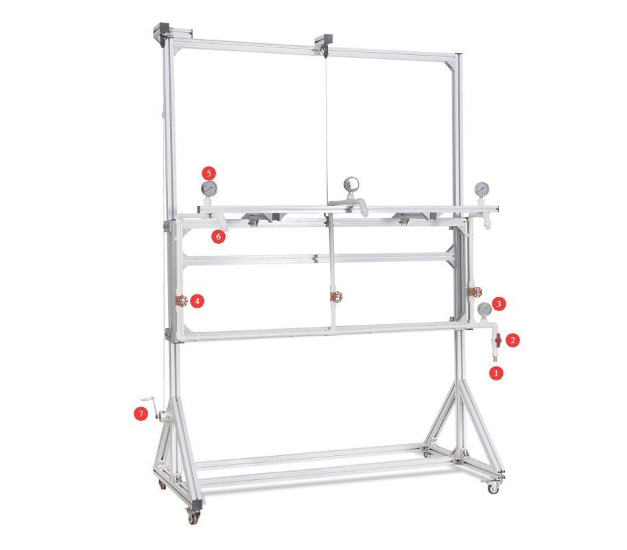
Figure 2
3.2 Water Sprinkling Test Apparatus
| No. | Note |
| ① | Inlet |
| ② | Inlet valve, used to control the water pressure to the sprinkler heads. When parallel to the water pipe, it is open; when perpendicular to the water pipe, it is closed. |
| ③ | Pressure gauge that displays the inlet water pressure to the sprinkler head |
| ④ | Sprinkler Nozzle |
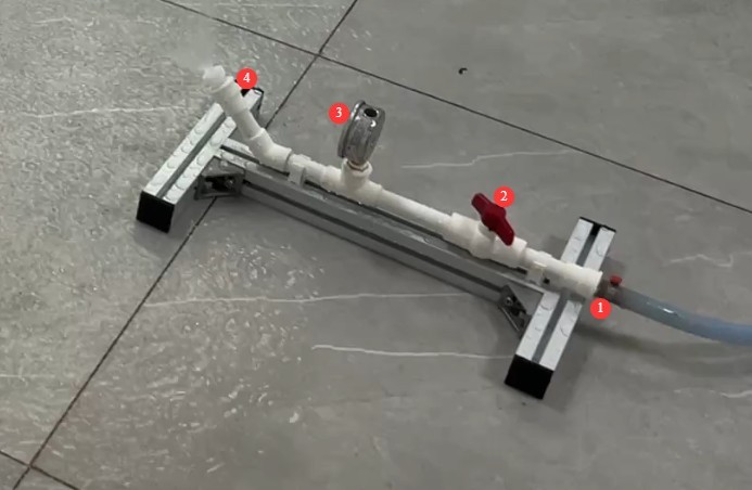
Figure 3
4. Preparations Before Testing (Refer to UL 1598)
4.1 Preliminary Adjustment of Test Water Pressure
4.1.1 Rain Test
Open the water inlet valve and the water faucet on the rain test apparatus;
Adjust the inlet valve and the three pressure-regulating valves to maintain the total inlet water pressure within the range of 50–150 kPa (i.e., 0.05–0.15 MPa); Ensure that the inlet water pressure at each rain simulation nozzle is stabilized at 34.5 kPa (i.e., 0.0345 MPa; the standard allows a tolerance of ±5 percent; for ease of operation, it may be adjusted directly to the 0.035 MPa mark);
Once the system has been properly commissioned, there is no need to adjust the water inlet valve or pressure-regulating valve; simply turn off the water supply faucet. During testing, you can simply turn on the water supply faucet.
4.1.2 Water Spray Test
Open the inlet valve and the water faucet on the sprinkler test apparatus;
Adjust the inlet valve so that the water pressure at the sprinkler head remains stable at 140 kPa (i.e., 0.14 MPa, with a standard tolerance of ±5%);
Once the system has been properly commissioned, there is no need to adjust the inlet valve or pressure-regulating valve; simply close the inlet faucet. During testing, you can simply open the inlet faucet.
4.2 Placement of Sample Luminaires
4.2.1 Rain Test
Secure the sample in its actual installation position to ensure that all surfaces exposed to the outdoors are evenly sprayed.
The distance from the nozzle to the center of the sample is approximately 1.4 meters (56 inches), and the sample is located in the spray focal area. The height of the spray nozzle can be adjusted as needed using a hand lever.
4.2.2 Water Sprinkling Test
Applies only to outdoor luminaires installed at a height of less than 1.2 meters above the ground; secure them in their actual installation position to ensure that the bottom and sides are fully covered by upward-directed water jets.
The distance from the nozzle to the center of the sample is 914 mm (36 inches), and the distance from the nozzle to the bottom of the sample is 76–152 mm (3–6 inches).
5. JL-UL Water Spray Test Procedure (Reference: UL 1598)
5.1 Preheating the Test Luminaire
First, turn on the lamp and preheat the sample for 30 minutes.
5.2 Rain Test
| Steps | Duration | Status | Purpose |
| 1 | 1 hour | Get Wet Level, Lights On | Simulate normal operating conditions |
| 2 | 0.5 hours | Turn on when it rains; turn off the lights | Simulated Power Outage and Rain Exposure |
| 3 | 2 hours | Turn on when it rains; the lights come on | Continuous exposure to rain under simulated operating conditions (most severe) |
| 4 | 0.5 hours | Get Wet, Turn Off the Lights | Simulating Recovery After Rain |
5.3 Water Spray Test (if required)
The procedure and duration are the same as for the rain test.
5.4 Evaluation of Test Results
| Evaluation Criteria | Specific Requirements |
| 1 | A dielectric voltage withstand test was conducted immediately after the test, with no breakdown or flashover. |
| 2 | Open the casing to inspect: Ensure no water droplets come into contact with live parts (including internal wires). |
| 3 | A small amount of water may accumulate inside the enclosure (if drainage holes are provided), but it must not form a conductive path. |
| 4 | Water droplets are permitted to adhere to the surface of plastic-insulated wires made of non-woven materials (except for special wire types). |
| 5 | The sample is functioning normally, with no electrical malfunctions or safety hazards caused by water leaks. |
6. Daily Maintenance and Care of Equipment
6.1 Daily Cleaning and Maintenance
6.1.1 Nozzle Cleaning
Clean the UL nozzle regularly to prevent blockages caused by foreign objects; we recommend cleaning it once a month;
Cleaning Instructions: Gently remove the nozzle with a wrench, then use a high-pressure air gun to blow out the inside of the nozzle, or wipe the outlet with a cotton swab dipped in clean water. Do not poke the nozzle with hard objects to avoid damaging the nozzle orifices.
6.1.2 Pipe Cleaning
After each test, drain any residual water from the piping to prevent scale and sediment buildup;
Rinse the corrugated tubing with clean water once every quarter. After rinsing, drain all the water, let it air dry, and then store it.
6.1.3 Maintenance of Equipment Surfaces
Wipe down the surface of the equipment with a dry cloth once a week. If there are stubborn stains, gently wipe them with a neutral cleaner, then dry with a dry cloth. Do not use corrosive cleaners on the equipment to avoid damaging metal and plastic parts.
6.2 Regular Maintenance
When the equipment is not in use for an extended period, it is necessary to periodically flush the system with water to prevent the buildup of impurities in the pipes and clogs in the nozzles. It is recommended to perform a flushing test once every two weeks; during the test, adjust the water pressure to 34.5 kPa and allow water to flow from each nozzle for 1 to 2 minutes.
6.3 Equipment Storage and Maintenance
6.3.1 Storage Environment Requirements
The equipment must be stored in a dry, well-ventilated environment away from direct sunlight to prevent the PVC piping and plastic components from deteriorating. The storage environment should have a temperature of 5–35°C, a relative humidity of ≤80%, and be free of corrosive gases and dust.
6.3.2 Storage Requirements
When storing the equipment, be sure to lock the brakes on the swivel casters to prevent the equipment from sliding and damaging the piping. For long-term storage, cover the entire unit with a dust-proof cloth to prevent dust from entering the nozzles and piping.
7. Troubleshooting and Resolving Common Problems
| Fault Symptoms | Possible Causes | Procedure |
| No water comes out of the nozzle, or the water pressure is below the required level | Insufficient inlet water pressure; inlet valve or pressure-regulating valve not properly adjusted; clogged nozzle | Increase the inlet water pressure, adjust the inlet valve/pressure-regulating valve, and refer to Section 6.1.1 for cleaning the nozzle. |