
 English
 中文简体
中文简体 English
 Русский
 Español
 Português
 Türkçe
 العربية
 Deutsch
 Polski
 Italiano
 Français
 한국어
한국어 ไทย
ไทย Tiếng Việt
 日本語
日本語





























Apparatus for Torsion Test on Pins
User's Manual
Applicable LISUN models: GNGPL-3633
1. Basic Understanding of Equipment
1.1 Scope of Application
The GNGPL-3633 Apparatus of BS1363-1 Figure 33 is a specialized testing device designed to verify the torsional mechanical strength of 13A plug pins and insulated disconnectors (ISOD). By applying a constant torque specified in the standard to a single prong and maintaining it for a specified duration, the device assesses whether the prong undergoes permanent deformation due to torsion. This determines whether the plug’s mechanical safety performance meets the required standards. It can be used in plug type testing, factory inspections, and third-party testing scenarios.
1.2 Applicable Standards
This equipment is designed and manufactured in strict accordance with the requirements of Clause 13.9.6 and Figure 33 of BS 1363-1:2023, “13 A Plugs, Socket-Outlets, Adapters, and Connection Units—Part 1: Rewirable and Non-rewirable 13 A Fused Plugs – Specification,” and fully complies with the test methods, dimensional parameters, and acceptance criteria specified in the standard, thereby meeting the compliance testing requirements for British Standard 13 A plugs.
1.3 Operating Principle
The equipment secures the plug body using a clamping mechanism, ensuring that the plug’s axis remains coaxial with the torque-loading shaft; The torque tube, adapted to the plug pin end, is fitted onto the plug pin under test. A precise torsional torque is applied to the torque tube via the torque loading module, transmitting the torque along the plug pin’s axis to its base, thereby simulating the torsional external forces experienced by the plug pin during actual use.
1.4 Downloading Electronic Documents
We have already emailed you the download links for the digital user manual, calibration certificate, warranty card, and other documents at the time of shipment. Please download them promptly. If you have not received the email, please contact us to request the download links again.
2. Safety Precautions
2.1 Environmental Safety
Operating temperature: 10°C to 35°C; relative humidity: 30% to 75%, non-condensing;
Placement Requirements: A level, stable surface free of vibration.
2.2 Operational Safety
Wear protective gloves during operation to avoid cuts on your hands from the sharp edges of the latch;
During the torque application process, do not touch the rotating torque components with your hands;
When clamping the specimen, ensure that the plug is fully secured and does not wobble to prevent the specimen from flying out or shifting during torque loading;
The torque tube and pin must be fully and properly engaged. Do not initiate torque loading under off-center loading or when the pin is inserted at an angle, to prevent the torque tube from popping out or the pin from breaking;
Do not conduct tests outside the specified torque range to prevent damage to the torque sensor or mechanical components.
3. Equipment Overview
3.1 Standard Diagram
See Figure 3-1 (taken from BS 1363-1:2023, Figure 33).

Figure 3-1
3.2 Photographs of the actual items
See Figure 3-2.
| Number | Note |
| ① | 20N weight, used to apply torque |
| ② | Torque tube, corresponding to BS 1363-1:2023, Figure 33, Item 3 |
| ③ | A pulley with a radius of 50 mm; during the test, a weight is hung on the pulley to generate a test torque of 1 N·m. |
| ④ | Plug fixture, corresponding to BS 1363-1:2023, Figure 33, Item 1; position adjustable |
| ⑤ | During the test, the torque tube attached to the pin is secured here to transmit torque to the test specimen. |
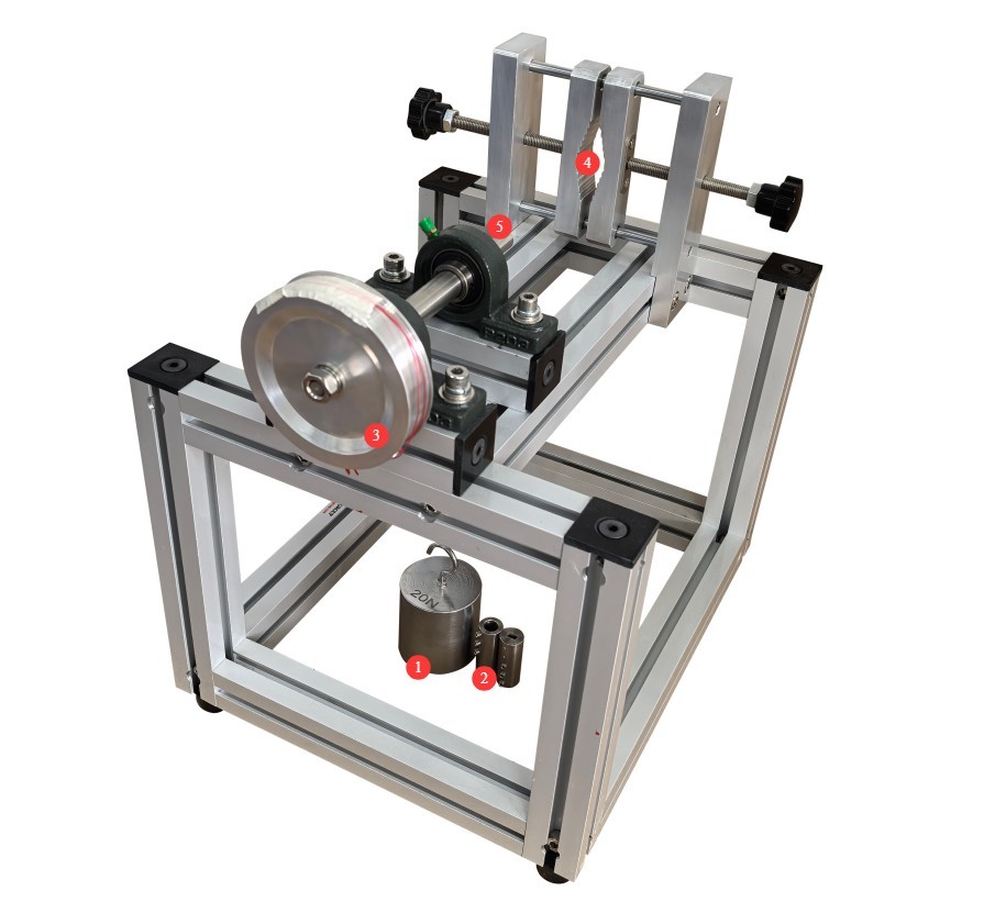
Figure 3-2
4. Preparations Before the Test
4.1 Sample Preparation
4.1.1 Specimen Requirements
Test specimens shall be complete, finished plugs with no surface damage or deformation, and with pins that show no obvious bending or corrosion; re-connectable plugs must be fully assembled according to the manufacturer’s instructions, while non-re-connectable plugs must be tested in their as-delivered condition; it is recommended to prepare three parallel specimens for each test set to ensure the reproducibility of test results.
4.1.2 Sample Pretreatment
Before testing, the test specimens must be left to stand in the test environment for at least 4 hours to allow their temperature to equalize with the ambient temperature, thereby preventing temperature differences from affecting the test results.
4.2 Preparation of Gauges
4.2.1 Figure 5: Gauge Calibration
Confirm that the BS 1363-1:2023 Figure 5 plug gauge being used is within its calibration validity period, that the working surface of the gauge is free of scratches and deformation, and that its dimensional accuracy complies with the requirements of the BS 1363-1 standard.
4.2.2 Pre-use Verification of Gauges
Be familiar with the method for using gauges as specified in Clause 13.2.1 of BS 1363-1: Place the gauge vertically, with the mating surface of the plug parallel to the end face of the gauge; apply a vertical force of no more than 10 N to the plug and observe whether the plug enters the gauge completely.
5. Plug Torque Test Procedure
5.1 Overview of the Test Procedure
5.1.1 Description of Test Logic
In accordance with Clause 13.9.6.1 of BS 1363-1:2023, the test follows the sequence “individual testing of each pin → forward torque loading → gauge inspection → reverse torque loading → repeat gauge inspection,” with each pin tested in turn.
5.1.2 Description of the Test Sequence
It is recommended to conduct the tests in the following order: “phase pin → neutral pin → ground pin.” Each pin must undergo torsion tests in both the forward and reverse directions, and must be inspected with a gauge after each torsion test.
5.2 Equipment Operation
5.2.1 Clamping of Plugs and Torque Tubes
As described in Section 3.2, secure one end of the torque tube to the equipment.
Secure the test specimen plug to the equipment’s plug fixture, adjust the fixture’s position, and align the plug so that the axis of the plug under test is perfectly aligned with the axis of the torque tube. Refer to BS 1363-1:2023, Figure 33, and insert the plug into the torque tube. Ensure that the plug is securely fastened.
Finally, secure the fixture in place.
5.2.2 Applying Torque
Hang the weights on opposite sides of the pulley to apply torque in different directions to the pin. Confirm that the torque direction is the first torsional direction (clockwise), and that the torque is maintained for 60 seconds.
After the test is complete, change the orientation of the weights to ensure that the torque is applied in the second torsional direction (counterclockwise), and maintain the torque for 60 seconds.
After completing the forward and reverse tests on a single pin, test the remaining pins one by one following the same procedure.
6. Post-Test Procedures
6.1 Device Reset
Remove the plug, torque tube, and all weights to prevent any force from being applied when the device is not being tested.
6.2 Sample Preparation
Separate the samples that passed and failed the test, label them clearly, and avoid any confusion.
6.3 Cleaning and Tidying Up the Test Site
Use a lint-free, soft cloth to wipe away dust and debris from the surfaces of fixtures, brackets, and devices. Do not rinse the equipment directly with water.
Organize the tools and weights on the workbench, arrange them neatly, and clean up any debris generated during the experiment.
7. Routine Maintenance and Care
7.1 Regular Maintenance
Every three months, apply a small amount of neutral lubricating grease to critical parts, such as the oil wheel bearings, the clamping screw, and the slide rails, to prevent rust and jamming.
7.2 Long-Term Storage and Maintenance
After completing routine maintenance, cover the entire machine with a dust cover and store it in a dry, well-ventilated warehouse; apply rust-preventive oil to the weights, torque tubes, and fixtures to prevent rust and deformation.
7.3 Calibration Interval Requirements
To ensure the accuracy and reliability of the device, it is recommended that it be sent periodically to a qualified third-party metrology laboratory for calibration. The recommended calibration interval is 12 months. Users may determine the specific calibration interval based on frequency of use, environmental conditions, and quality system requirements.
8. Troubleshooting and Resolving Common Issues
| Fault Symptoms | Possible Causes | Procedure |
| Low torque, pulley jamming | Dust buildup in bearings, insufficient lubrication, foreign objects lodged in bearings | Try again after removing dust from the bearings, replenishing the lubricating grease, and removing any foreign objects from the clearances. |
| Rust on fixtures, weights, and torque sleeves | The humidity is too high | If there are minor signs of rust, sand the area with fine-grit sandpaper and apply rust-preventive oil; if the rust significantly affects accuracy, the part must be replaced. |