English
 中文简体
中文简体 English
 Русский
 Español
 Português
 Türkçe
 العربية
 Deutsch
 Polski
 Italiano
 Français
 한국어
한국어 ไทย
ไทย Tiếng Việt
 日本語
日本語





























High Temperature Chamber
User's Manual
Applicable LISUN models: GW-010、GW-013、GW-015、GW-020、GW-225、GW-225-400、GW-225-AH、GW-500、GW-500-400
1. Basic Understanding of Equipment
1.1 Key Technical Specifications
| LISUN Model | GW-225 | GW-500 | GW-010 | GW-015 | GW-020 |
| Working Compartment Dimensions (cm) | 50 × 60 × 75 | 70 × 80 × 90 | 100 × 100 × 100 | 100 × 100 × 150 | 100 × 100 × 200 |
| Temperature Range | Room temperature to 250 degrees (customizable to room temperature to 300 degrees) | ||||
| Variability/Uniformity | ±0.5°C/±1°C | ||||
| Rate of temperature rise | 1.0°C to 3.0°C per minute | ||||
1.2 Unboxing and Checking the Contents
1.2.1 Unpacking and Visual Inspection
When unpacking the equipment, handle it gently to avoid scratching the exterior casing with sharp tools. After unpacking, first inspect the exterior of the main unit to ensure there is no visible deformation, dents, or peeling paint, and that the control panel, gauges, and buttons are free of damage or looseness. If you discover any damage or deformation to the equipment or accessories, do not power it on. Contact LISUN customer service immediately.
1.2.2 Host-type
1 High Temperature Chamber:
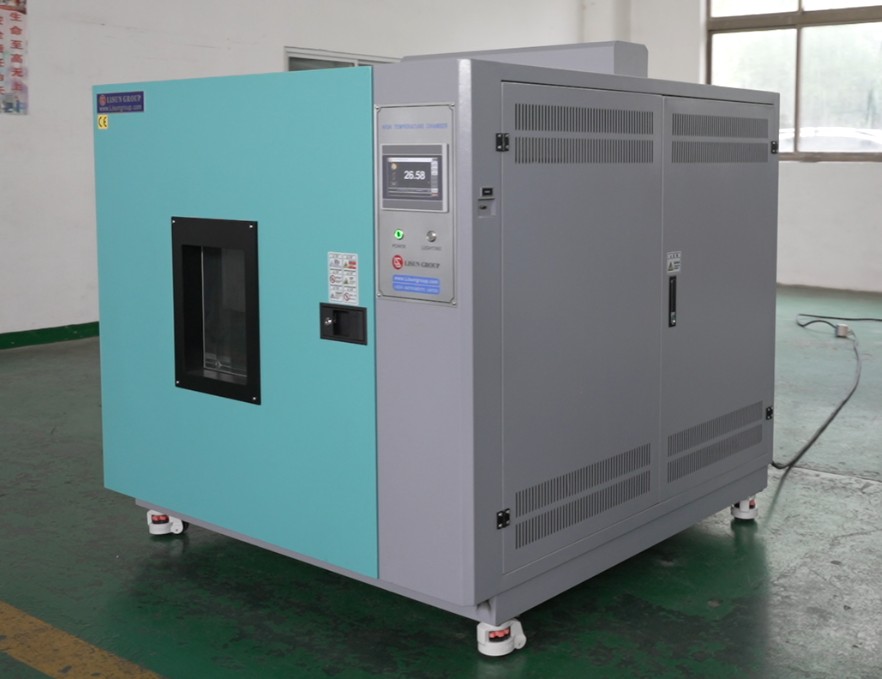
Figure 1
1.2.3 Consumables and Accessories
Open the accessory box. Standard accessories include: a spare solid-state relay, rubber plugs, and spare fuses.
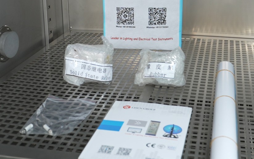
Figure 2
Download links for the digital user manual, warranty card, and other documents have been sent via email. Please download them as soon as possible. If you missed the email, please feel free to contact us to request a new download link.
1.3 Description of Equipment Structure
1.3.1 Front and Interior of the Test Chamber
① Control panel; ② Test chamber door; ③ Temperature probe; ④ Air duct; ⑤ Shelves and shelf supports (samples must be placed on the shelves and not in direct contact with the inner wall of the test chamber).
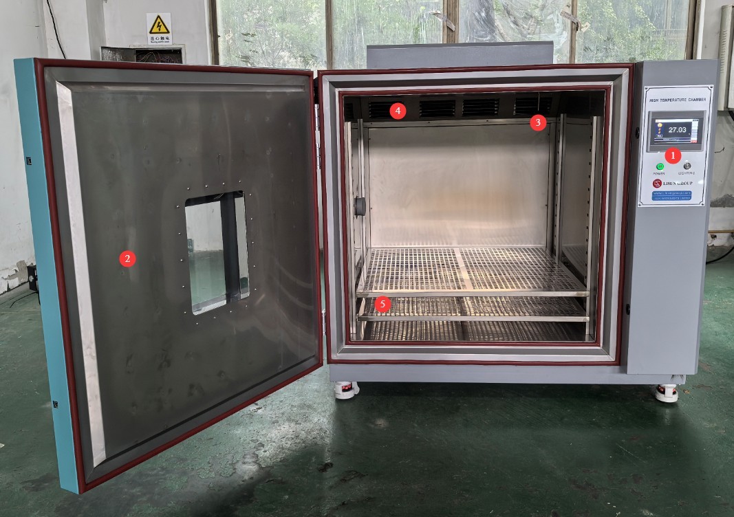
Figure 3
1.3.2 Rear and Side Views of the Test Chamber
① Power cord; ② Ventilation openings (there are multiple ventilation openings on the back and top of the unit; do not block or seal them during use); ③ Side opening: If the test specimen has cables connected to the outside of the test chamber, they can be routed through this opening.
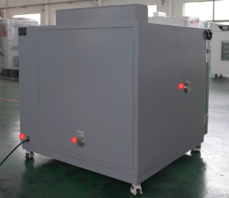
Figure 4
2. Safety Precautions
2.1 Electrical Safety
2.1.1 Power Connection
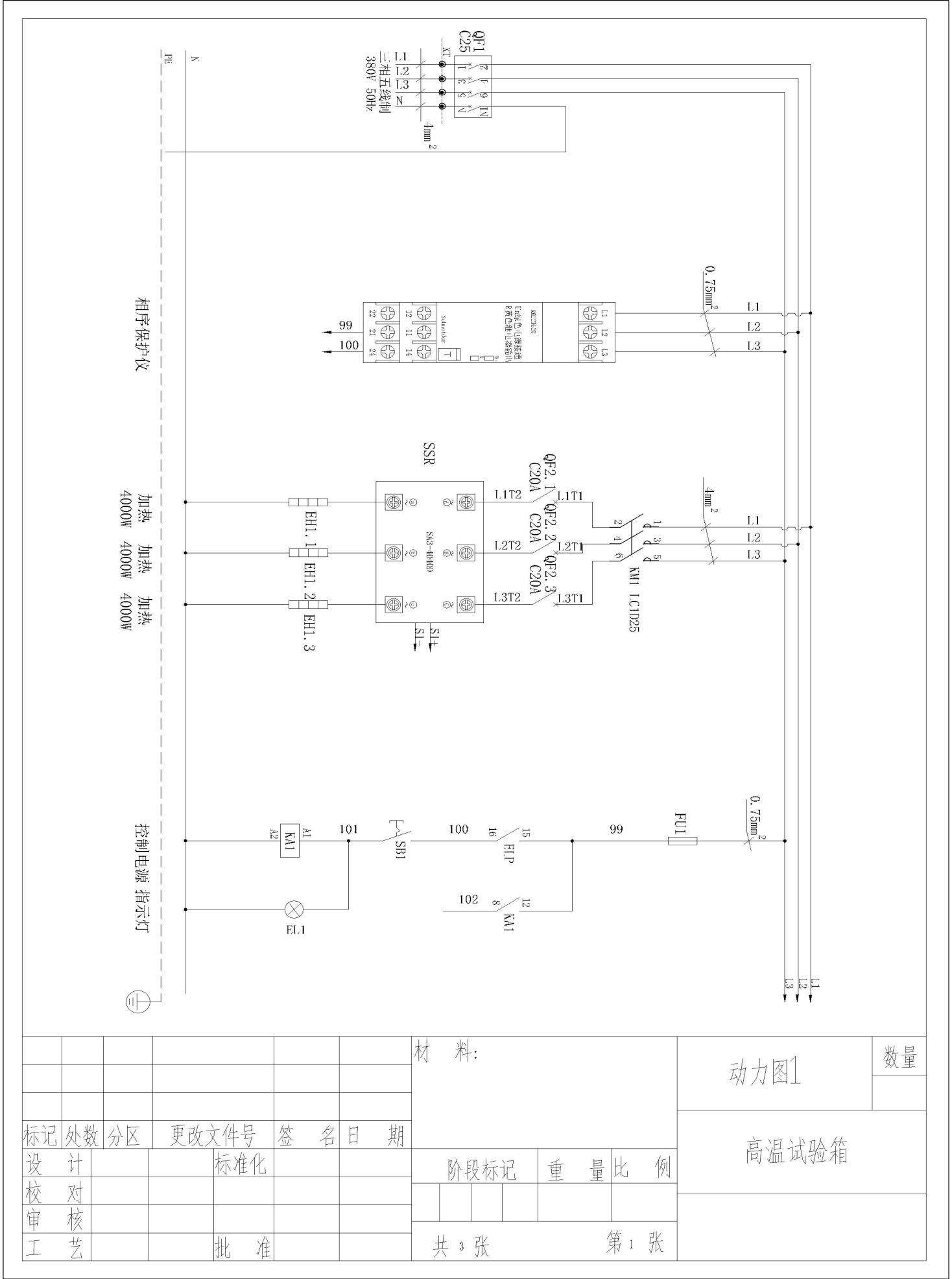
The equipment must be powered by a dedicated circuit with a three-phase, five-wire system rated at AC 380 V, 50 Hz (or 60 Hz, optional). Multiple units must not share a single power source to prevent voltage drops that could cause abnormal equipment performance or unplanned downtime. Before connecting the power supply, ensure the power is turned off. When making connections, strictly distinguish between the live wires (L1, L2, L3), neutral wire (N), and ground wire (PE). The wiring sequence must comply with the requirements of the equipment’s electrical schematic; reversing the live and neutral wires is strictly prohibited.
The equipment is equipped with a phase sequence protector. Before applying power after wiring, check the phase sequence: If the “Un” green light and the “R” yellow light on the phase sequence protector are both lit, the wiring is correct; If only one of the lights is on, or none are lit, this indicates reverse phase. Turn off the main power supply, swap the positions of the two adjacent live wires (L1 and L2), and then check again;
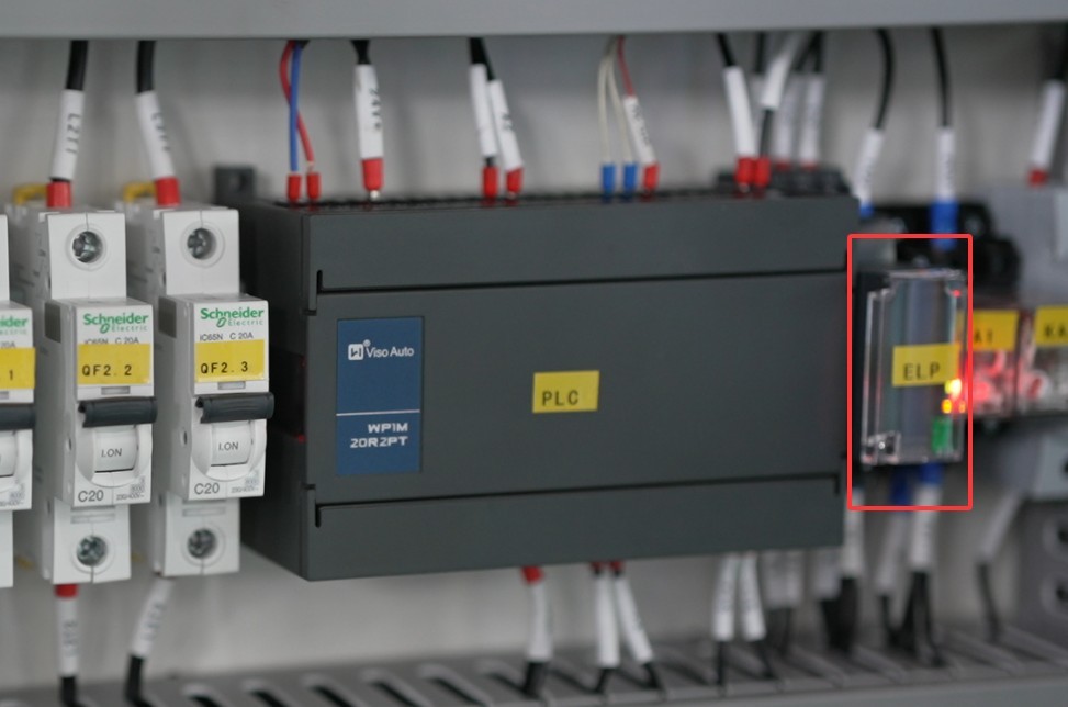
Figure 5
After completing the wiring, pull firmly on the terminal to ensure the connection is secure and there is no looseness.
2.1.2 Grounding Specifications
The equipment must be reliably grounded, with a grounding resistance of ≤50 Ω. Do not use gas pipes, non-metallic water pipes, or the neutral wire as a substitute for the grounding wire. After grounding is complete, use a Grounding Resistance Tester to measure the grounding resistance. Power may only be applied after confirming that it meets the requirements, to prevent electric shock, equipment malfunctions, or measurement errors caused by poor grounding.
2.1.3 Contraindications for the Procedure
Before wiring, inspecting, or maintaining the equipment, you must turn off the circuit breaker on the back of the unit and disconnect the main power supply. Only proceed after confirming that there is no residual voltage;
Do not operate the equipment’s power switch, touchscreen, or instrument buttons with wet hands to avoid the risk of electric shock;
Do not place any foreign objects (such as tools or paper) inside the electrical control cabinet to prevent dust or foreign objects from causing short circuits or damaging components;
Do not plug in or unplug power cords or signal cables while the equipment is running to prevent short circuits that could damage the controller or electrical components.
2.2 Operational Safety
2.2.1 Test Specimen Restrictions
The equipment must not be used for testing flammable, explosive, toxic, or highly corrosive substances (such as alcohol, gasoline, strong acids, and strong alkalis). Since the equipment is not equipped with explosion-proof devices, the use of such substances may cause fires, explosions, or corrosion of the equipment;
If the test specimen generates heat (such as during power-on testing of electronic components), an external, independent power source must be provided for the specimen. Do not use the equipment’s own power supply directly to avoid overloading the equipment’s circuitry;
The sample volume must not exceed 80% of the test chamber’s capacity, and the weight must not exceed the specified load capacity of the shelves (30 kilograms per shelf) to prevent shelf deformation or disruption of the temperature cycling process.
2.2.2 Operational Safety
While the equipment is in operation, non-professionals are prohibited from disassembling or repairing it. In the event of a malfunction, contact after-sales service personnel or operate the equipment under the guidance of a technician;
Avoid opening the chamber door as much as possible during the test. Opening the door when the temperature is high (≥80°C) may cause burns to the operator and disrupt the temperature equilibrium inside the chamber, thereby affecting the test results. If it is necessary to open the door, wear heat-resistant gloves and safety goggles, open the door slowly, and wait until the temperature inside the chamber has stabilized before proceeding;
Do not set the temperature above the range specified for the equipment; exceeding the temperature limit may cause the heating element to burn out or even result in a fire;
If the equipment triggers an alarm (the touchscreen automatically switches to the alarm code screen), immediately stop the test and troubleshoot the problem (see “Chapter 7: Troubleshooting and Resolving Common Problems”). Do not force the equipment to restart; operating the equipment before the problem is resolved may cause further damage.
2.2.3 Prohibited Conduct
Do not open the control cabinet door while the equipment is running to avoid electric shock from coming into contact with internal high-voltage components;
Do not disassemble core components such as the temperature sensor (PT100 platinum resistance thermometer) or heating elements without authorization. Modifying the equipment will void the warranty and may result in safety incidents;
Do not place heavy objects (such as tools or accessories) on top of the equipment to avoid damaging the equipment panel or impairing heat dissipation;
Do not pile flammable items (such as cardboard boxes, plastic wrap, etc.) around the equipment. Keep the equipment’s ventilation openings clear to prevent the risk of fire.
2.3 Environmental Safety
2.3.1 Installation Requirements
The equipment must be installed in an air-conditioned room where the ambient temperature is maintained between 5°C and 25°C and the relative humidity is ≤85%. If the ambient humidity is high, condensation may form near the equipment door and test ports; in such cases, improve room ventilation or use a dehumidifier;
The installation site must be free of high concentrations of dust, corrosive gases (such as sulfur dioxide and chlorine), and flammable or explosive atmospheres. Direct sunlight must not be allowed to shine on the equipment to prevent corrosion of the equipment housing and deterioration of electrical components;
Keep the device away from areas with significant temperature fluctuations, such as near vents or room entrances, to prevent the device’s temperature control accuracy from being affected.
2.3.2 Space Requirements
The distance between the equipment enclosure and the wall, as well as surrounding structures (such as other test equipment and shelving), must be at least 1500 mm to ensure unobstructed ventilation at the equipment’s heat dissipation openings (rear and sides);
At least 2000 mm of space must be left at the equipment door opening to ensure that the door can be opened in any direction, facilitating the placement and removal of samples;
2.3.3 Horizontal Placement
The equipment must be placed on a level surface. Use a spirit level to ensure the equipment is level: Place the spirit level on the top surface of the equipment and make sure the bubble is centered. Note: The height of the following types of legs must be adjusted to ensure the test chamber is level:
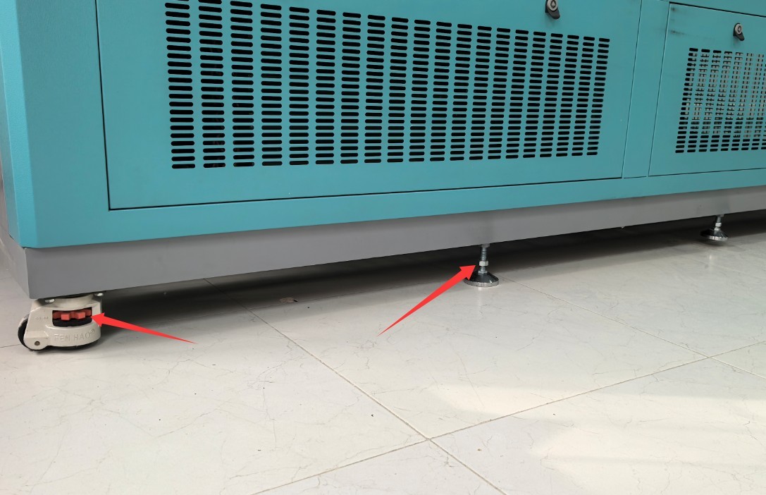
Figure 5.1
If the equipment is tilted, it may compromise the structural stability of the test chamber, cause uneven temperature distribution inside the chamber, or even result in poor door sealing, thereby affecting test results and the equipment’s service life.
2.4 Other
For matters not covered in this manual, please proceed with caution or contact us.
3. Preparations Before the Test
3.1 Connecting the Power Cord
See 2.1.1.
3.2 Sample Placement
For sample restrictions, see Section 2.2.1.
Note: If the sample requires the use of a cable, please reseal the side opening on the outside of the test chamber using a rubber plug, as shown in the figure below:
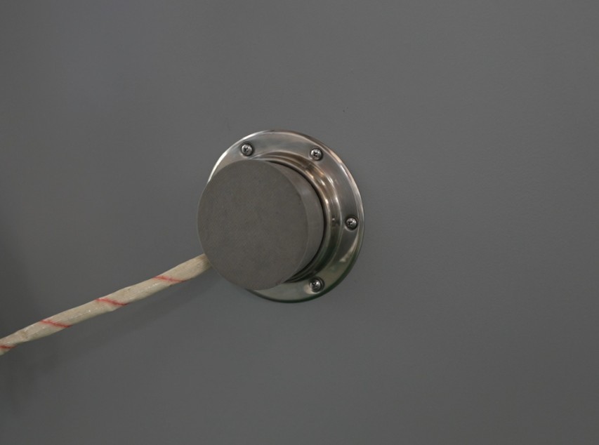
Figure 6
Samples must not come into contact with the inner walls of the test chamber; do not touch or cover the temperature probes; and do not block the airflow. Samples must be securely fastened, and must not move during the test.
3.3 Closing the Cabinet Door
Make sure the box door is closed and the lock is secured. For double doors, first press down on the left door and lock it, then press down on the right door and lock it.
3.4 Starting Up the Test Chamber
Press the “Power” button on the control panel on the front of the device. The touchscreen program will enter standby mode. Ensure there are no alarms; if there are any, refer to Chapter 7 for troubleshooting.
4. Program Operation via the Touchscreen on The High Temperature Chamber
4.1 Introduction to the Main Screen
The system automatically enters the monitoring screen when it starts up. Click “MAIN” in the upper-right corner to access the main screen.
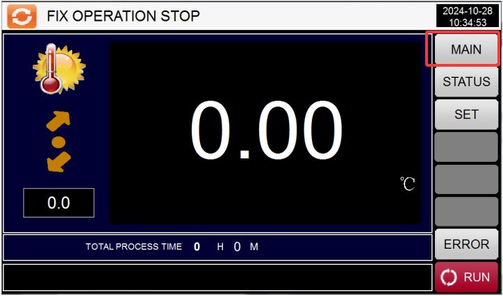
Figure 7
From left to right and top to bottom, they are: ① Curve display; ② Monitoring screen; ③ Operation settings; ④ Program group settings; ⑤ Scheduling settings; ⑥ Display settings.
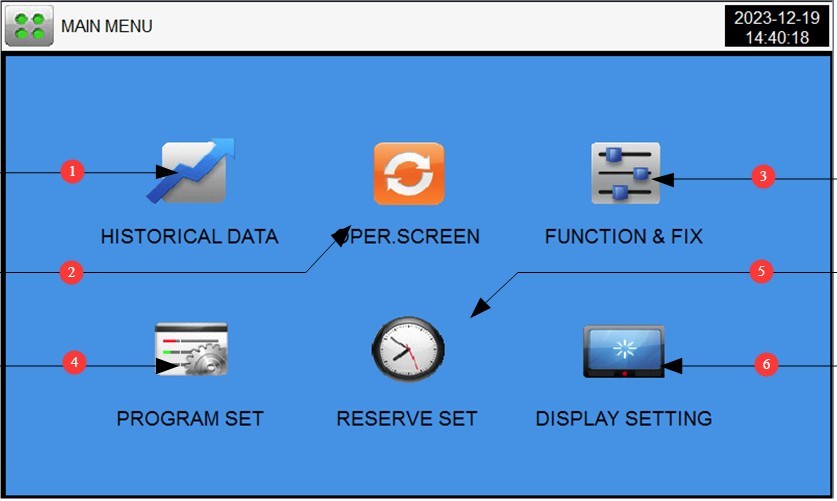
Figure 8
4.2 Operation Settings
Go to the “Operation Settings” screen. ① Select the test operation mode: FIX (fixed value) or PRO (program); ② Set the test completion action: no action or return to room temperature. If you want the system to automatically return to room temperature, set the room temperature range.
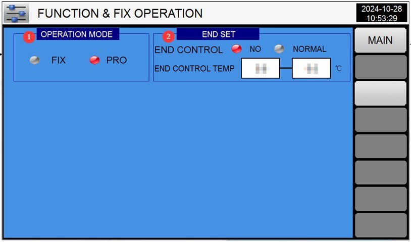
Figure 9
Note: The High Temperature Chamber has only a heating function; it does not have a cooling function. The test chamber cannot cool down from high to low temperatures on its own in a short period of time; manual intervention by opening the chamber is required, provided safety is ensured.
4.3 Appointment Settings
Go to the “Scheduled Settings” screen. ① The left column displays the current time; ② in the right column, enter the scheduled time. Then press the “RESERVE” button on the far right until it turns red—this confirms that the schedule has been successfully set, and the test chamber will automatically begin the test at the scheduled time.
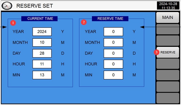
Figure 10
4.4 Display Settings
Go to the “Display Settings” screen. ① Select the display language; ② Power-off recovery mode (Stop: After a power outage during operation, the system returns to the “Stop” state when power is restored; Cold Start: After a power outage during operation, the system restarts from the first segment when power is restored; Hot Start: After a power outage during operation, the system continues from the segment where operation was interrupted before the outage and restores the system to its pre-outage state when power is restored).
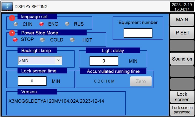
Figure 11
4.5 Fixed-Value Operation (Single Temperature and Humidity Point Test)
4.5.1 Accessing the Fixed-Value Settings
Select “Fixed Value” in “Operation Settings.” Go to the “Monitoring Screen,” then click the “Settings” button on the right to open the “Fixed Value Settings” screen.
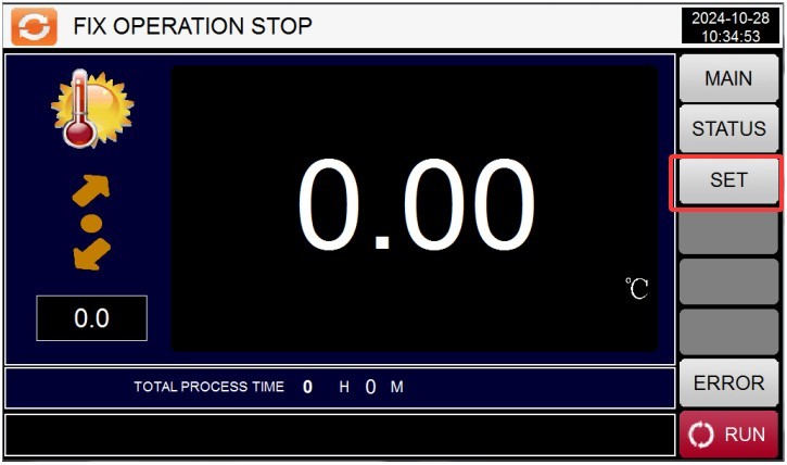
Figure 12
4.5.2 Parameter Settings
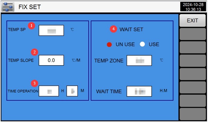
Figure 13
① Temperature Setting: Enter the target temperature (see Section 1.1 for the configurable temperature range).
② Temperature ramp rate: Unless a custom ramp rate has been specified, use the default value of 0. The test chamber will operate using the automatic ramp rate.
③ Timed Operation: Enter the test duration (e.g., 2H; range: 0–9999H); when set to 0, the test must be stopped manually.
④ Wait Setting: If the wait function is selected, the test time will not begin until the test chamber reaches the set temperature. You must also set the wait tolerance (the temperature is considered to have been reached if it falls within this tolerance) and the wait time (if the test chamber has not reached the set temperature by the end of the wait time, the test time will automatically begin).
4.5.3 Starting the Calibration Test
After verifying that the parameters are correct, return to the monitoring screen and click the “Run” button in the lower-right corner.
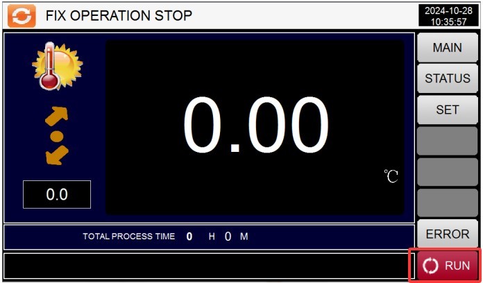
Figure 14
4.6 Program Operation (Multi-Stage Temperature Cycling Test)
4.6.1 Program Group Settings Screen
① Program number: You can set up to 100 programs, numbered 1 through 100, ensuring no numbers overlap with existing programs; ② Enter the program name; ③ Edit the program; ④ Set the loop; ⑤ Set the wait time.
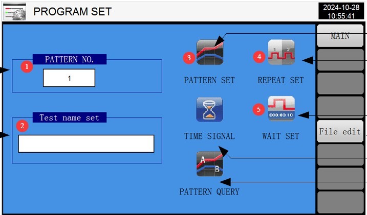
Figure 15
4.6.2 Accessing the Program Editing Screen
① Test segment number; each program can have up to 99 test segments. ② Temperature setting. ③ Test duration setting.④ The relay is set to automatic operation; no changes are needed to the parameters here; ⑤ Switch segment numbers; ⑥ Insert or delete a segment; ⑦ Enter the number of segments to run in this program. For example, if you only want to run the first four segments of the program, enter 4. Please enter the correct value; otherwise, the program will malfunction; ⑧ Return to the program group settings screen.
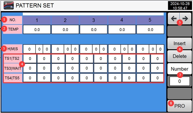
Figure 16
Example: If you need to perform the following tests: Step
1: Temperature 50°, test duration 3 hours;
Step 2: Temperature 150°, test duration 5 hours.
The settings should be:
| NO. | 01 | 02 | 03 | 04 | 05 … |
| Temperature | 50° | 150° | 0 | ||
| Time | 0.01.00 | 3.00.00 | 0.01.00 | 5.00.00 | |
NO 01: Transition phase—the time required to reach the target temperature.
NO 02: Actual test duration: 3 hours.
NO 03: Transition phase—the time required to reach the target temperature.
NO 04: Actual test duration—5 hours.
In other words, for each set of temperature and humidity conditions, two phases must be configured: the first is the transition phase—the time it takes for the test chamber to reach the set temperature—and the second is the test duration at that temperature.
Note: In the examples above, the transition phase is set to only 1 minute. The equipment has a wait function; even if the set time is short, the equipment will reach the set value before proceeding to the next phase. This configuration minimizes the equipment’s preparation time to save on test time.
The High Temperature Chamber has only a heating function and no cooling function. Therefore, the test program should be set to run from low to high temperature. If the program is set to run from high to low temperature, the chamber may not be able to cool down from high to low temperature on its own within the specified time; in such cases, a user must manually open the chamber to intervene, while ensuring safety.
4.6.3 Loop Settings Screen
① Number of loops for the current program; the default value is 1, meaning the test stops immediately after the current program is completed; ② Linked program number; this specifies whether the system should automatically proceed to another program for continued testing after the current program is completed. Enter 0 if this is not required; ③ Loop mode for the current program’s test segments; the default value is 0, meaning no repetition—the test proceeds sequentially from the first segment to the last.
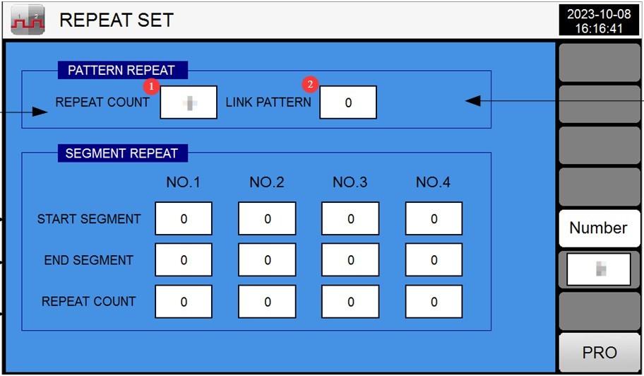
Figure 17
Example: The figure below means that after the current program has been run twice, it will automatically proceed to Test Program 3 to continue testing.
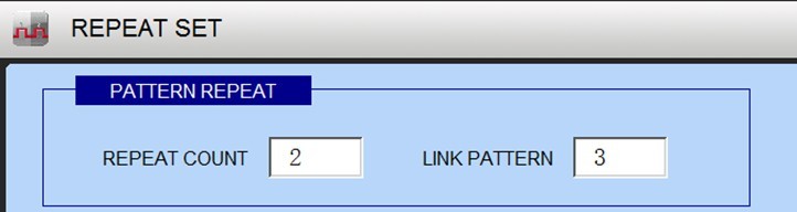
Figure 18
The diagram below shows that the current test sequence for the program is 01>02>03>04>05>03>04>05>02>03>04>02>03>04>05>06>07…
meaning testing begins with the first segment.sections 3 through 5 are repeated twice, followed by sections 2 through 4 being repeated twice, and then the remaining test sections are completed in sequence.
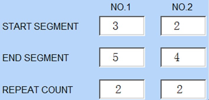
Figure 19
Based on the logic above, you can configure the program’s test parameters to meet your own testing requirements.
Note: The High Temperature Chamber has only a heating function; it does not have a cooling function. If any step requires lowering the temperature from high to low, the test chamber may not be able to cool down from high to low on its own within the specified time; in such cases, manual intervention by opening the chamber is required, provided that safety is ensured.
4.6.4 Wait for the Settings Screen
① Select “ALL” to enable the wait function for all test segments; ② Wait zone error value; ③ Maximum wait time.
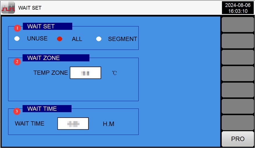
Figure 20
4.6.5 Startup Test
After verifying that the parameters are correct, return to the monitoring screen and click the “Run” button in the lower-right corner.
4.7 Test Operation and Monitoring
4.7.1 Monitoring Screen
The monitor screen displays the set temperature and the current actual temperature.
4.7.2 Real-Time Fault Monitoring
If a fault occurs, the touchscreen automatically switches to the “Real-Time Fault Display Screen.”
Check the error codes and refer to Chapter 7 for troubleshooting and resolution; click “Mute” to turn off the buzzer, and click “Reset Errors” once the issue has been resolved.
4.7.3 Viewing and Exporting Curves
Tap the “Curve Display” screen on the main screen to view the real-time temperature curve.
Insert the USB drive, click “Download,” and the curve data will be saved to the USB drive in CSV format (which can be opened and analyzed on a computer).
Tap “Clear History” (press and hold for 5 seconds) to delete old curve data (use with caution).
5. Post-Test Procedures
5.1 Equipment Shutdown Procedures
5.1.1 Program Termination
If the program ends normally: The device operates according to the “Program End Mode” (e.g., “Return to Ambient Temperature,” automatically cooling down to the set ambient temperature range).
To stop the process early: Click the “Stop” button on the monitoring screen, and the device will enter standby mode.
5.1.2 Power-Off Procedures
Verify that the device is in standby mode (not running), and turn off the power switch on the device’s control panel.
Turn off the main power switch.
5.2 Sample Retrieval and Handling
Wear heat-resistant gloves (even if the sample has “returned to room temperature,” it may still retain residual heat), open the chamber door, and slowly remove the sample.
Inspect the condition of the samples (e.g., appearance, performance) and record test data (temperature, humidity, time, changes in the samples).
If there is any liquid residue on the sample, wipe it clean with a lint-free cloth to avoid contaminating the work area.
5.3 Equipment Cleaning
Cleaning the Inner Chamber: Wipe the inner walls and shelves of the chamber with a lint-free cloth moistened with alcohol to remove any residual sample stains (do not spray water or alcohol directly onto the surfaces).
Cleaning the Refrigerator Door: Wipe down the door gasket (to remove dust) and check that the gasket is not deformed (if there are stains, wipe them off with a damp cloth).
Cleaning the Outer Case: Wipe the equipment housing with a dry cloth to remove surface dust (do not use gasoline or organic solvents, as this may cause the paint to peel).
Cleaning the Touchscreen: Wipe it with a dry cloth to remove fingerprints and ensure touch sensitivity.
5.4 Test Records
Fill out the equipment usage log, recording the following information: test date, program group, sample name, runtime, malfunctions (if any), and operator.
Organize test data (such as graphs and sample reports) and file them for safekeeping.
6. Daily Maintenance and Care of Equipment
6.1 Regular Cleaning and Maintenance
6.1.1 Routine Cleaning (After Each Test)
| Maintenance Projects | Maintenance Instructions | Important Notes |
| Inner Chamber of the Chamber | Wipe with an alcohol-soaked lint-free cloth to remove stains | Do not wash with water; avoid exposing electrical components to moisture. |
| Sealing Strip | Wipe with a dry cloth and check for any deformation or damage. | If the rubber seal is worn out (and no longer seals properly), contact customer service to have it replaced. |
| Touchscreen | Wipe with a dry cloth to remove fingerprints and dust | Do not scratch the screen with sharp objects. |
| Ventilation opening | Wipe off surface dust with a dry cloth and ensure proper ventilation. | Do not block the ventilation openings (to prevent overheating) |
6.1.2 Regular Cleaning
| Maintenance Projects | Maintenance Cycle | Maintenance Instructions | Objectives and Requirements |
| Temperature Sensor | Monthly | Use a soft-bristled brush to remove dust from the sensor surface | Measurement accuracy within ±2°C/±3% RH |
| Ground Resistance | Every 3 months | Grounding Resistance Tester Inspection | Ground resistance ≤ 50 Ω |
| Electrical Components | Every 6 months | Open the control cabinet door and check that the relays and terminal blocks are secure. | No oxidation, no loose connections; the circuit breaker is functioning normally. |
6.2 Long-Term Suspension for Maintenance (Suspended for More Than 1 Month)
6.2.1 Disabling Preprocessing
After completing all tests, turn off the power and unplug the unit as described in 5.1.2;
Thoroughly clean the equipment (inner tank, outer casing, and electrical cabinet);
Open the door of the cabinet and allow the inner liner to air dry naturally (to prevent mold growth);
Remove all test specimens and shelves (if any) from the equipment and store them separately.
6.2.2 Maintenance During Downtime
Power on the unit at least once a month (for 30 minutes, to allow the circulation fan and controller to run) to prevent components from becoming damp;
Inspect the exterior of the equipment to prevent dust buildup; you may cover it with a dust cover (made of breathable material);
Inspect the storage environment to avoid moisture, high temperatures, or corrosive gases.
6.2.3 Pre-Reactivation Checks
Remove the dust cover and clean the equipment;
Check that the power lines and grounding are in good condition;
After turning on the power, check whether the controller, fan, and heating system are operating normally;
Conduct one short-duration test at a fixed setting (e.g., 50°C for 30 minutes) to verify that the equipment is functioning properly before proceeding with the formal test.
7. Troubleshooting and Resolving Common Problems
7.1 Touchscreen Alarms
| Troubleshooting Codes | Possible Causes | Solution |
| PT1 Temperature Sensor Malfunction | The PT100 probe is faulty; its resistance at room temperature is 110 Ω; a point on the PLC module is faulty; the PT100 wiring is loose. |
Replace the PT100 probe; repair or replace the PLC module; rewire |
| X2 Temperature Control: Over-Temperature Protection | Corrosion at the connection points or exposure to water; uncontrolled heating, resulting in an abnormal rise in temperature; the motor is not running, preventing heat from dissipating from inside the heating element; the impeller has fallen out, preventing heat from dissipating from inside the heating element |
Clean or rewire; check the solid-state output; check whether there is 220V voltage between the red and yellow wires of the motor; if there is no voltage, replace the motor; if there is voltage, replace the capacitor; reinstall the impeller |
| X3 Test Chamber Overtemperature Protection | The over-temperature protection setpoint is lower than the controller’s setpoint | 1. Adjust the over-temperature protection setpoint to match that of the controller |
7.2 Controller-Related Faults
7.2.1 Controller without a digital display
| Fault Symptoms | Possible Causes | Solution |
| The controller screen is black; there is no display at all. | 1. The power plug is not properly connected; 2. The power outlet has no power, or there is a missing phase in the three-phase power supply; 3. The wiring at the controller’s power supply terminals has come loose; 4. Internal controller malfunction; 5. The control cabinet door is open, causing the power circuit breaker to trip. | 1. Plug the power cord securely into the outlet; 2. Check the outlet’s power supply and use a multimeter to verify that the three-phase power is normal; 3. Turn off the main power, open the electrical cabinet, check the wiring at the controller’s power supply terminals (e.g., 24 VAC), and retighten the connections; 4. Contact the manufacturer to repair or replace the controller;5. Close the control cabinet door, reset the circuit breaker (inside the control cabinet), and verify that it has closed. |
7.2.2 The controller displays garbled characters or the numbers flicker
| Fault Symptoms | Possible Causes | Solution |
| The numbers appear as garbled characters or are unstable | 1. Loose connection between the controller and the sensor; 2. The platinum resistance thermometer (temperature sensor) is damaged or has a poor solder joint; 3. Significant power supply interference (e.g., high-power equipment nearby); 4. Internal controller malfunction | 1. Disconnect the main power supply, inspect the sensor terminals, and retighten them; 2. Replace the platinum resistance sensor (model PT100, 3-wire system, lead resistance ≤ 10 Ω), and resolder it; 3. Eliminate power supply interference (e.g., keep the unit away from high-power equipment and use a regulated power supply);4. Contact the manufacturer to repair or replace the controller |
7.3 Heating System Malfunctions
7.3.1 The Equipment Does Not Heat Up
| Fault Symptoms | Possible Causes | Solution |
| The temperature does not rise during operation, and the heating indicator light does not come on. | 1. Over-temperature protection activated (buzzer alarm); 2. Set temperature is lower than the current actual temperature; 3. Solid-state relay failure; 4. Heating element failure; 5. Open circuit in the platinum resistance thermometer (no signal from the sensor); 6. Fuse in the heating circuit blown | 1. Check the over-temperature protection setpoint, reset it (to 20°C higher than the test temperature), and press the [Fault Reset] button; 2. Reset the temperature (to a value higher than the current actual temperature);3. Disconnect the main power supply and use a multimeter to test the solid-state relay; replace it if damaged; 4. Measure the resistance of the heating element (normally several tens of ohms); replace it if damaged; 5. Check the platinum resistance wire connections and replace any open-circuit platinum resistance elements; 6. Replace the heating circuit fuse (4A rating). |
7.3.2 Uncontrolled Heating (Continuous Rise in Temperature)
| Fault Symptoms | Possible Causes | Solution |
| The temperature has exceeded the set value and continues to rise | 1. The temperature setpoint is too high (exceeds the equipment’s upper limit); 2. The solid-state relay is stuck (cannot open); 3. The platinum resistance thermometer is shorted (abnormal sensor signal); 4. Controller malfunction (cannot output a stop signal) | 1. Immediately disconnect the main power supply and reset the temperature (to a value ≤ the equipment’s upper limit; for example, GW-010 ≤ 250°C); 2. Replace the solid-state relay; 3. Inspect the platinum resistance thermometers and replace any that are shorted; 4. Contact the manufacturer to repair or replace the controller. |
7.4 Abnormal Operating Conditions and Malfunctions
7.4.1 The Circulating Fan Is Not Running
| Fault Symptoms | Possible Causes | Solution |
| The fan is not rotating and is silent. | 1. The fan’s power connections have come loose; 2. The fan’s overcurrent protection has tripped (thermal relay tripped); 3. The fan motor is damaged; 4. The controller is not sending a fan start signal | 1. Disconnect the main power supply, inspect the fan’s terminal blocks, and retighten them; 2. Reset the thermal relay (inside the electrical cabinet) and check whether the fan is jammed; 3. Measure the resistance of the fan motor (which should normally be several tens of ohms); if damaged, replace it; 4. Check the fan control parameters on the controller and contact the manufacturer for troubleshooting. |
7.4.2 Poor Door Seal (Temperature Leakage)
| Failure Symptoms | Possible Causes | Solution |
| Significant temperature fluctuations during operation; slow heating | 1. The door gasket is worn out or damaged; 2. The door hinges are loose, causing the door to be crooked; 3. The door latch is loose and does not close tightly | 1. Replace aged or damaged weatherstripping; 2. Adjust the cabinet door hinges and tighten the screws to ensure the door is vertical; 3. Adjust the position of the latch to ensure the weatherstripping is pressed tightly against the door when it is closed. |
7.5 Communication Failure (PLC No Response)
7.5.1 Communication Interruption (Screen displays “PLC no response”)
| Fault Symptoms | Possible Causes | Solution |
| Communication between the touchscreen and the PLC has been interrupted, and control is not possible. | 1. The communication cable (RS-485) is loose or disconnected; 2. The communication cable is damaged (e.g., broken or shorted); 3. PLC power supply failure; 4. Mismatched communication parameters (e.g., baud rate, address) | 1. Disconnect the main power supply, check the RS-485 communication cable terminals, and retighten them; 2. Replace the damaged communication cable (use shielded cable to reduce interference); 3. Check the PLC power supply (e.g., 24V) to ensure it is functioning properly;4. Check the communication parameters (baud rate, address) between the controller and the PLC to ensure they match, and contact the manufacturer for guidance on adjustments |
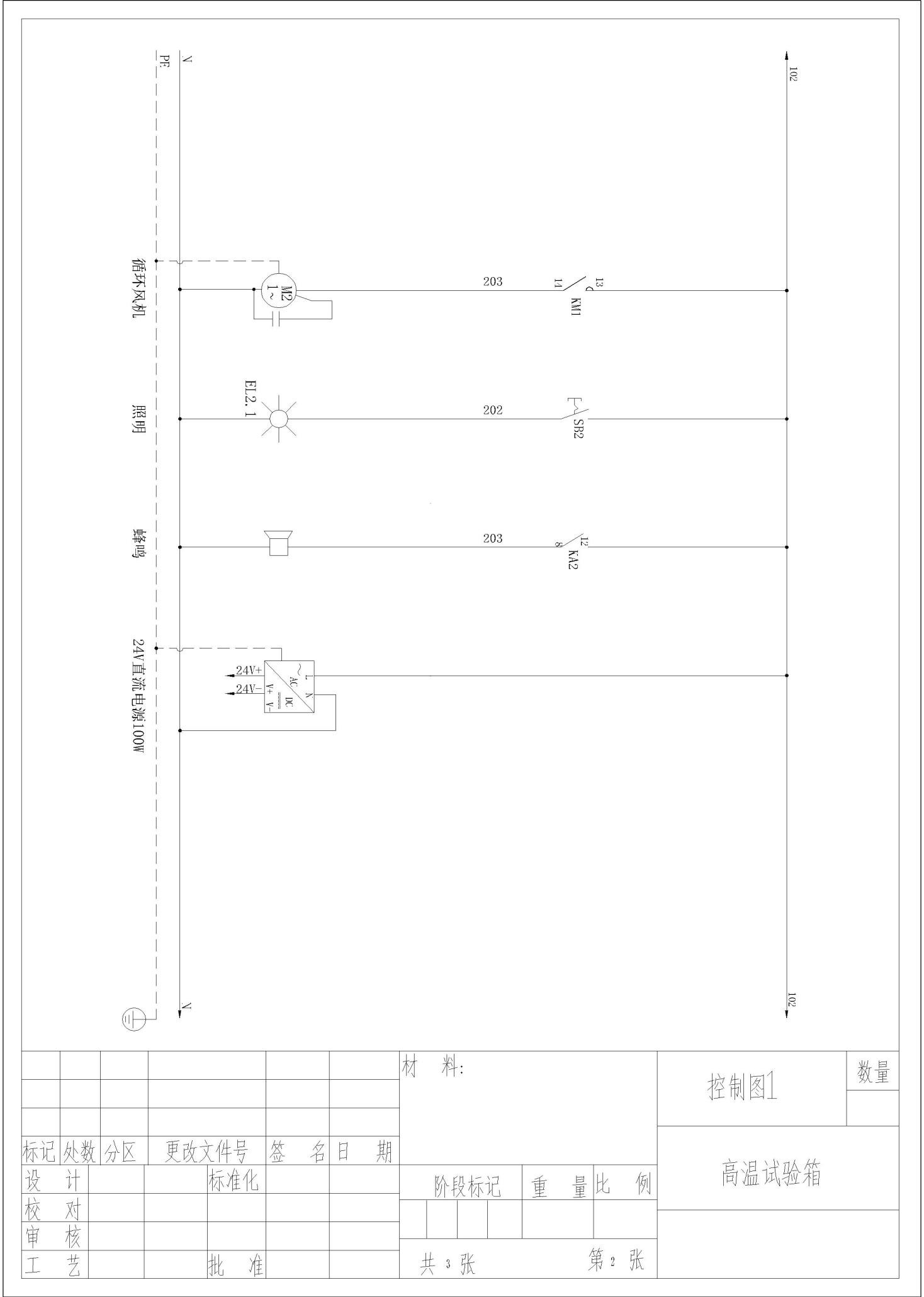
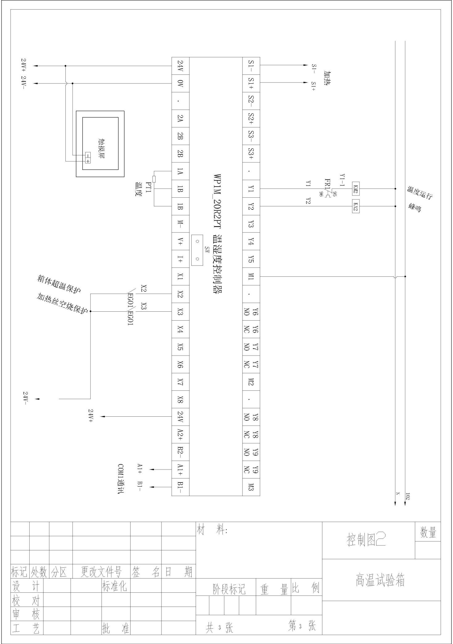
Appendix: Electrical Circuit Diagrams