
 English
 中文简体
中文简体 English
 Русский
 Español
 Português
 Türkçe
 العربية
 Deutsch
 Polski
 Italiano
 Français
 한국어
한국어 ไทย
ไทย Tiếng Việt
 日本語
日本語





























Optical Radiation Safety Test System
User's Manual
Applicable LISUN models: EN62471-A、EN62471-B、EN62471-C
1. Basic Understanding of Equipment
1.1 Key Technical Specifications
1.1.1 Wavelength Range
| Specifications/Model Numbers | EN 62471-A | EN 62471-B | EN 62471-C |
| Wavelength range | 200–800 nm | 200–1500 nm | 200–3000 nm |
1.1.2 Measurable Radiative Hazards
The hazards of photochemical UV exposure (weighted irradiance from 200 nm to 400 nm) primarily affect the skin and eyes;
The risks associated with near-ultraviolet exposure (irradiation in the 315 nm to 400 nm range) primarily affect the eyes;
Retinal blue light hazard exposure (weighted irradiance from 300 nm to 700 nm);
Retinal blue light hazard exposure (weighted radiation from 300 nm to 700 nm), primarily for small light sources;
Exposure to retinal thermal hazards (weighted radiation from 380 nm to 1400 nm);
Exposure to retinal thermal hazards (weighted radiation from 780 to 1400 nm), mild visual stimulation;
Exposure to infrared radiation (irradiance from 780 nm to 3000 nm) primarily poses a risk to the eyes;
Heat hazards (irradiation from 380 nm to 3000 nm) primarily affect the skin.
1.2 Equipment Configuration Verification
1.2.1 Unpack the product
When unpacking the device, handle it gently to avoid scratching the outer casing with sharp tools. After unpacking, first inspect the exterior of the device to ensure there is no visible deformation or dents, and that the buttons are not damaged or loose. If you notice any abnormalities with the device or its accessories, do not turn it on. Please contact us immediately.
1.2.2 Core Components
| Number | Note |
| ① Optical Test System | Consisting of the EsEuva spectral measurement probe, the photobiological radiance analyzer (comprising a retinal luminance meter, an LbLrLir spectral measurement probe, and an LrLir spectral measurement probe), the Eir irradiance probe (included only in EN 62471-C) and the Er irradiance probe (excluded only from EN 62471-A) |
| ② Industrial PC | Industrial PC, monitor, mouse, keyboard, etc. |
| ③ Cabinet | Includes the LS Series power meters, the DC Series Digital CC and CV DC Power Supply, and the LSP Series pure sine wave AC power supplies |
| ④ Optical Guide Rail | Assembled to meet length requirements. The optical test unit, the test sample, and the sample mounting stage are all mounted on guide rails. |
| ⑤ Sample Mounting Stage and Fixtures | Adjustable angle, used for mounting the sample under test |
| ⑥ Light Shield | Several; these can be placed between the sample under test and the optical test unit to prevent stray light from entering the probe. |
| ⑦ Other Components | Standard lamps, standard Pocket Illuminance Meters, and other auxiliary devices |
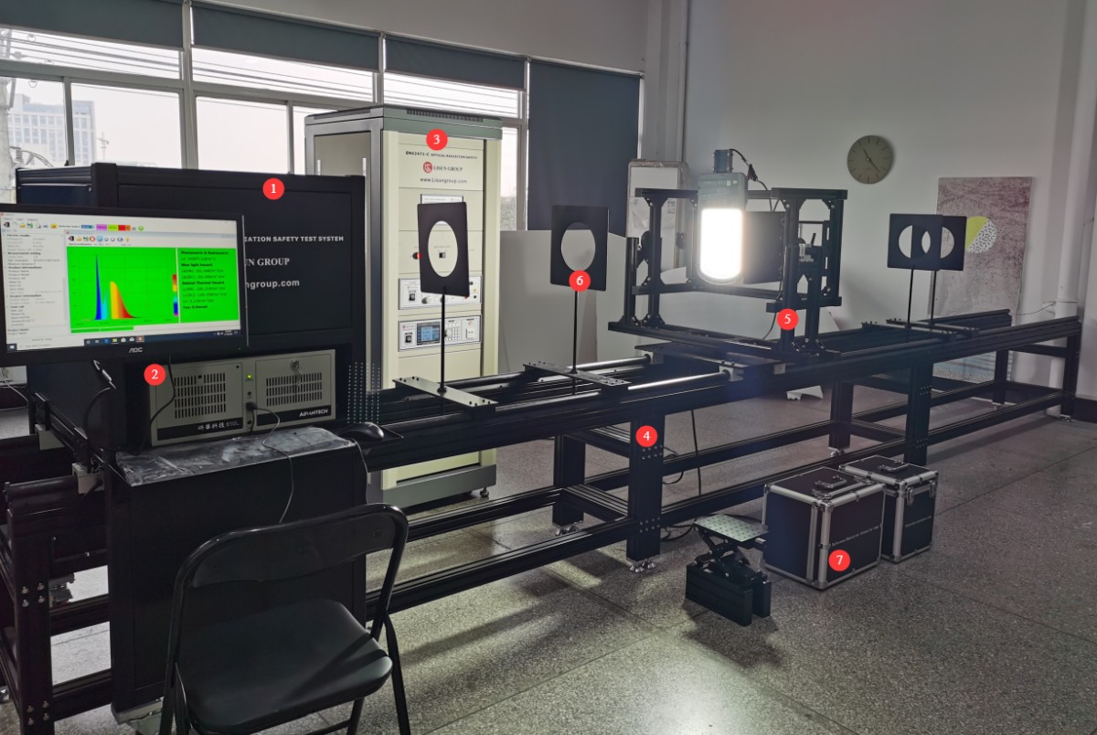
Note: This image shows the device only; for actual use, the device must be installed in a darkroom.
1.2.3 Downloading Electronic Documents
We have already sent the download links for the digital user manual, software, warranty card, and other materials via email at the time of shipment. Please download them as soon as possible. If you missed the email, you may contact us directly to request the download links again.
2. Precautions
2.1 Electrical Safety
The system must be connected to a stable AC power source of 220 V ±5%, with a frequency of 50 Hz or 60 Hz. Ensure proper grounding, with a grounding resistance of ≤4 Ω. Do not use the equipment if the power connections are loose or the cables are damaged.
2.2 Environmental Safety
When using the optical darkroom, the ambient temperature must be maintained at 25±1°C, and the relative humidity must be maintained between 10% and 65% RH;
Both the control room and the darkroom must be kept dry, well-ventilated, dust-free, and free of corrosive gases;
Avoid placing the device near strong magnetic or electric fields; it must be placed on a flat, sturdy surface.
2.3 Darkroom Operating Procedures
2.3.1 Darkroom Description
Please confirm that the darkroom has been constructed exactly according to the darkroom drawings we provided. If there are any discrepancies in the actual dimensions, please inform us before installing and commissioning the equipment so that we can adjust the plan to ensure that installation and commissioning proceed smoothly and that test results are accurate;
The interior of the darkroom must be completely painted matte black—that is, a non-reflective, pure black—including all walls, ceilings, floors, partitions, doors, and so on. A small number of components, such as lighting fixtures, air conditioning units, and power switches, may not be painted black, provided they do not appear in the optical path between the test sample and the optical testing system.
2.3.2 Precautions for Using the Darkroom
Remove your shoes or put on shoe covers when entering the darkroom to prevent dust from being brought in;
The test specimen must be securely mounted to prevent it from falling and damaging the equipment during testing;
During testing, the darkroom must remain sealed to prevent external light from interfering with the test results.
2.3.3 Precautions When the Darkroom Is Not in Use
Use a dust cap to seal the probe test port and prevent dust from entering;
Keep the darkroom closed; unauthorized persons are not permitted to enter, and prevent dust from entering the darkroom.
2.4 Operating Procedures for Calibration Accessories
The standard lamp has a lifespan of one year. If you are a laboratory and need to calibrate the system annually, you can purchase a new standard lamp; the Pocket Illuminance Meter must also be calibrated annually.
2.5 Safety Warnings Regarding Light Radiation
Do not look directly at the light source during calibration or testing.
3. Equipment Overview and Assembly
3.1 Cabinet
3.1.1 Cabinet Assembly
A wiring diagram is affixed to the inside of the cabinet’s rear door. Please install and connect the equipment inside the cabinet according to the wiring diagram.
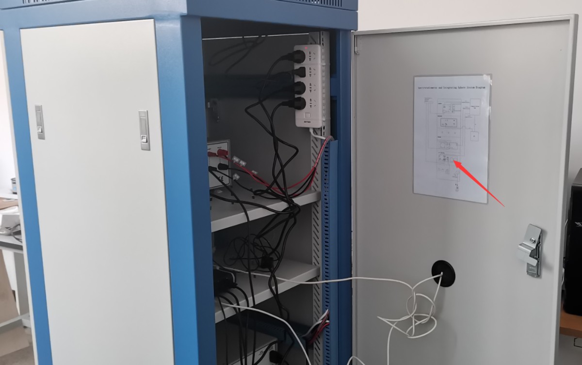
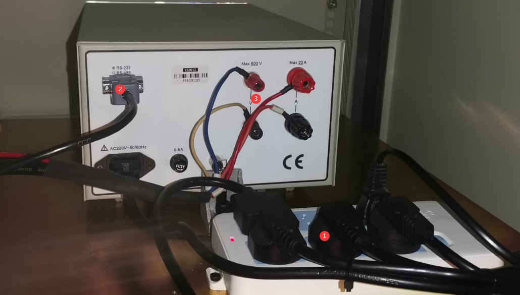
Wiring for the LS Series Power Meters.
| Number | Note |
| ① | Connect the power cords of all devices in the cabinet to the power strip inside the cabinet. |
| ② | RS-232 Communication Cable Connection |
| ③ | Connect the voltage and current sampling wires according to the drawings and the labels on the wires. |
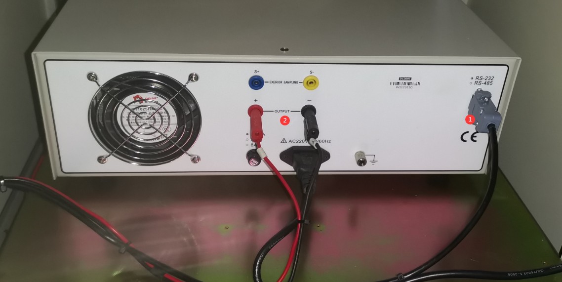
Wiring for the DC Series Digital CC and CV DC Power Supplies.
| Number | Note |
| ① | RS-232 Cable Connection |
| ② | Connect the output wires, paying attention to polarity. |
Wiring for the LSP Series Pure Sine Wave AC Power Supply.
| Number | Note |
| ① | RS-232 Cable Connection |
| ② | Output Cable Connection |
| ③ | Input power supply selection: The unit is factory-set to 220V. Do not adjust this setting arbitrarily, as doing so may damage the power supply. |
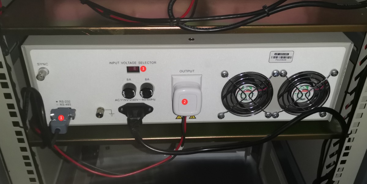
3.1.2 Introduction to the Cabinet
Front panel.
| Number | Note |
| ① | Main Power Switch for the Cabinet |
| ② | AC/DC switch that switches based on the lights installed on the optical rail |
| ③ | Internal/External Power Switch: The factory default is set to “Internal” (i.e., using the power supply inside the cabinet). If the power supply inside the cabinet is insufficient and you need to use an external power source, please switch to “External.” |
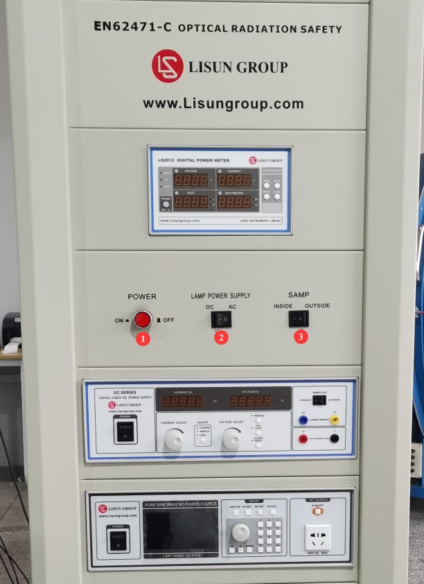
Back panel.
| Number | Note |
| ① | Includes one power cord (for connecting the cabinet to a suitable power source) and three RS232 communication cables (to be connected to the industrial PC as described in Section 3.2.4 below) |
| ② | The four-wire cable comes from the sample mount; refer to Section 3.2.3 later for connection instructions. |
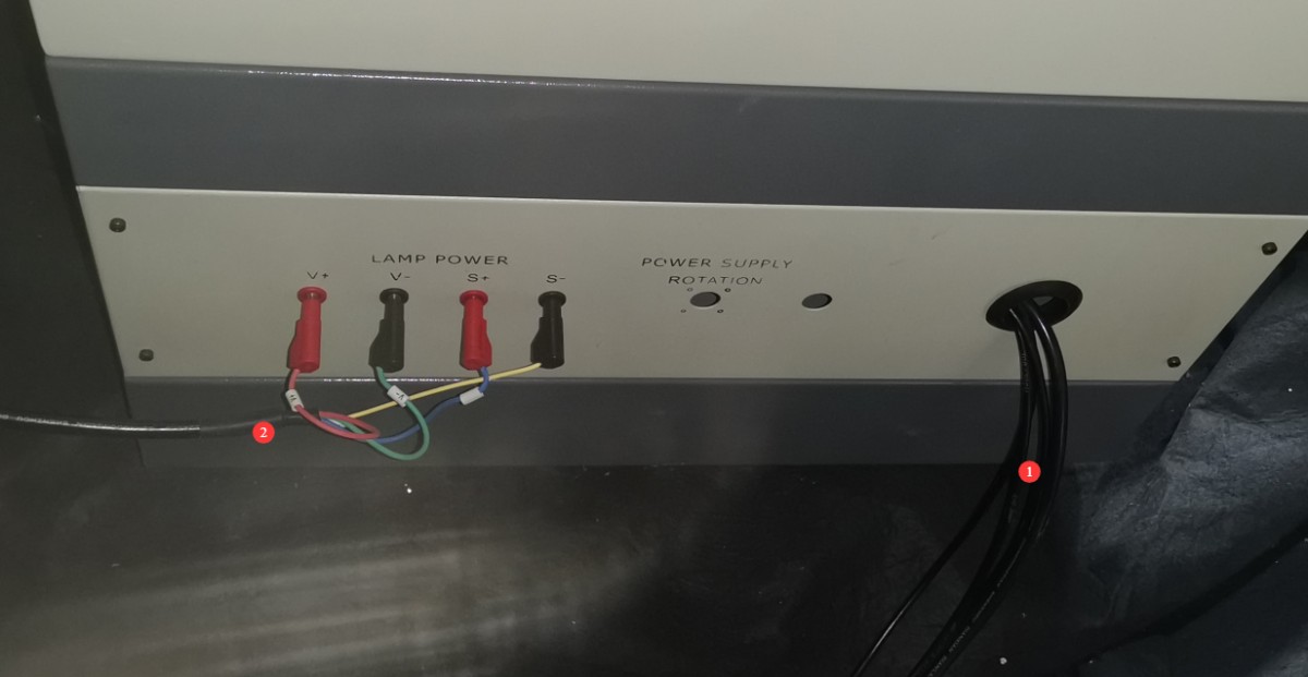
3.2 Assembly of Equipment Related to Optical Guides
3.2.1 Optical Guide Rails
| Number | Note |
| ① | One end of the optical guide rail has a hole |
| ② | The other end is the shaft |
| Insert the shaft into the hole to complete the assembly. Assemble all the optical rails together. | |
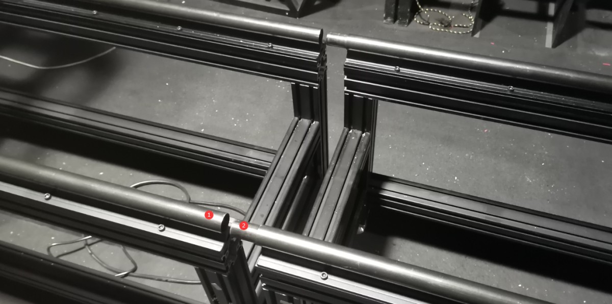
3.2.2 Optical Test System
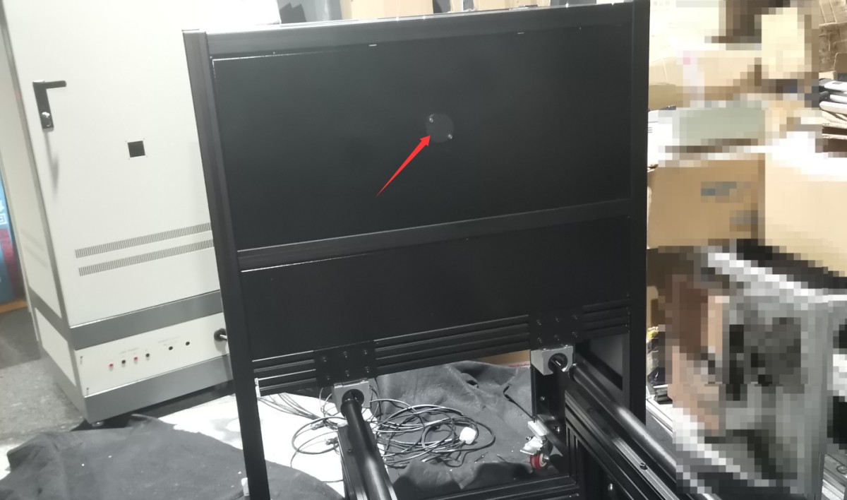
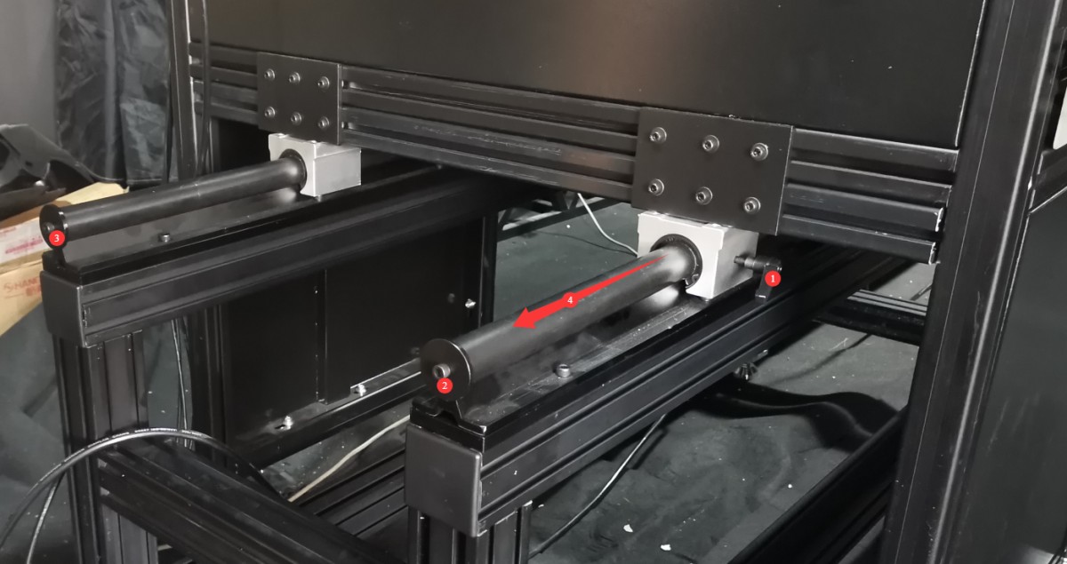
Slide the main unit into the rail from one end. Be careful when sliding it in; slide it in gently to avoid damaging the main unit’s slider bearings. The end with the probe test hole should be on the inside and should be slid in first.
| Number | Note |
| ① | First, loosen all the mounting screws on both sides of the optical test unit. |
| ②③ | Remove the two baffles from the optical guide rail at this point, slide the optical test unit into place, and then reinstall the two baffles. |
| ④ | Slide the optical test unit until it is flush against the two stops marked ① and ②, then retighten the mounting screws on both sides of the optical test unit. |
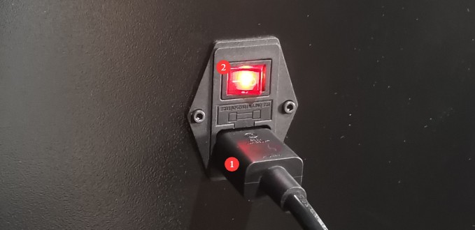
| Number | Note |
| ① | Connect the optical test unit’s power cord to the power strip inside the cabinet. |
| ② | Power Switch for the Optical Test Host |
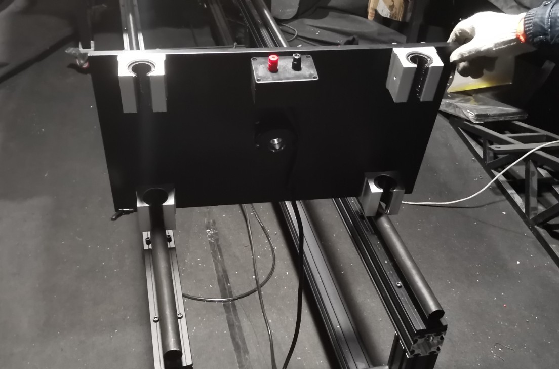
3.2.3 Sample Mounting Stations and Fixtures
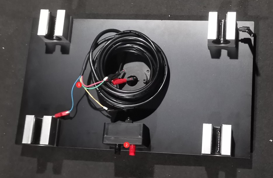
The image below shows the sample mounting platform.
| Number | Note |
| ① | Refer to Section 3.1.2 and connect the four-wire cable to the back of the cabinet. Make sure to match the labels on the cable with the markings on the cabinet’s terminal blocks when making the connections. |
| ② | The red and black terminals are used to connect a standard lamp or your test sample. |
Slide the sample stage into the optical rail from the other end.
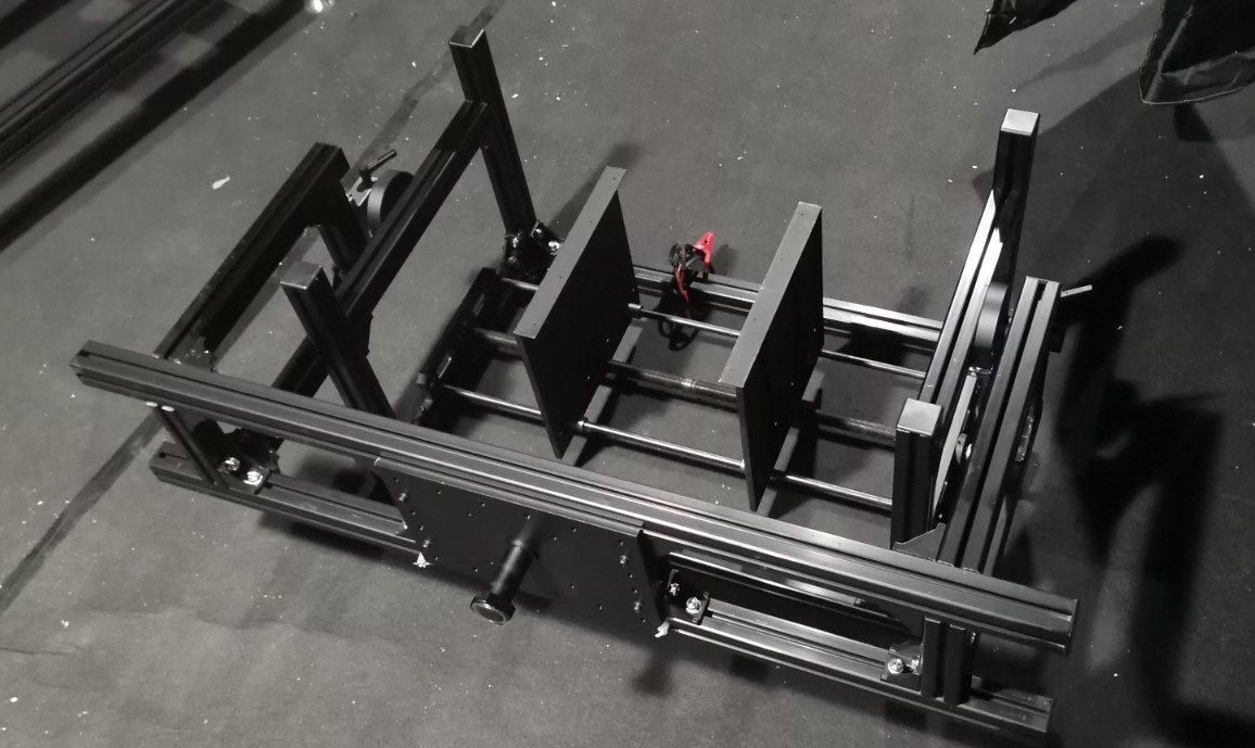
The figure below shows the fixture.
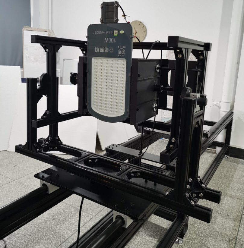
Install the fixture onto the sample mounting platform; the orientation of the fixture is adjustable. See the figure below for an example of the installation.
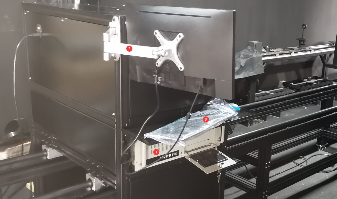
3.2.4 Industrial Computer
Assemble the industrial PC components as shown in the diagram below.
| Number | Note |
| ① | Host |
| ② | Monitor Stand and Monitor |
| ③ | Mouse, Keyboard |
Feed the three RS232 communication cables from the cabinet through the openings in the optical test unit:
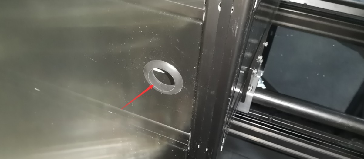
Connect to the industrial PC:
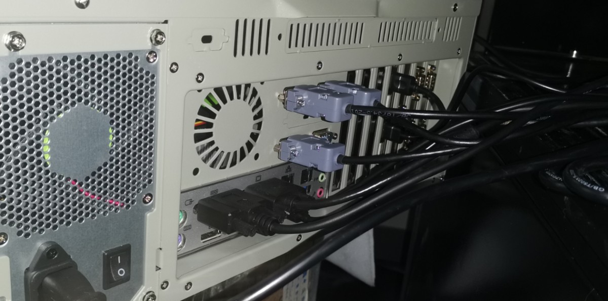
Note: Connect the power cords for the industrial PC and the display to the internal power distribution panel inside the optical test system.
3.2.5 Ruler
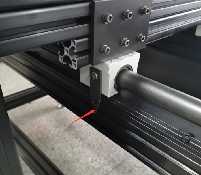
The accessories include an adhesive ruler that can be affixed to the assembled optical guide rail to make it easy to check the distance between the probe and the sample being measured.
A pointer on the main unit of the optical tester that indicates the probe’s position.
The pointer on the sample mounting stand indicates the mounting position of the sample under test.
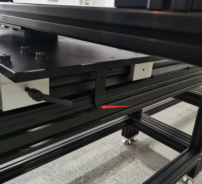
3.2.6 Power-On and Power-Off Sequence
Startup Sequence: First, turn on the cabinet’s main power switch. Then, power on the equipment inside the cabinet and the optical test host one by one. Finally, power on the industrial computer.
Shutdown procedure: First, shut down the industrial control computer; then, shut down the equipment inside the cabinet and the optical test host one by one; finally, turn off the main power switch for the cabinet.
4. Software Overview
Familiarize yourself with all the functional options on the software’s interfaces as described in Chapter 4, and then follow the instructions in Chapter 5 (How to Calibrate) and Chapter 6 (How to Test).
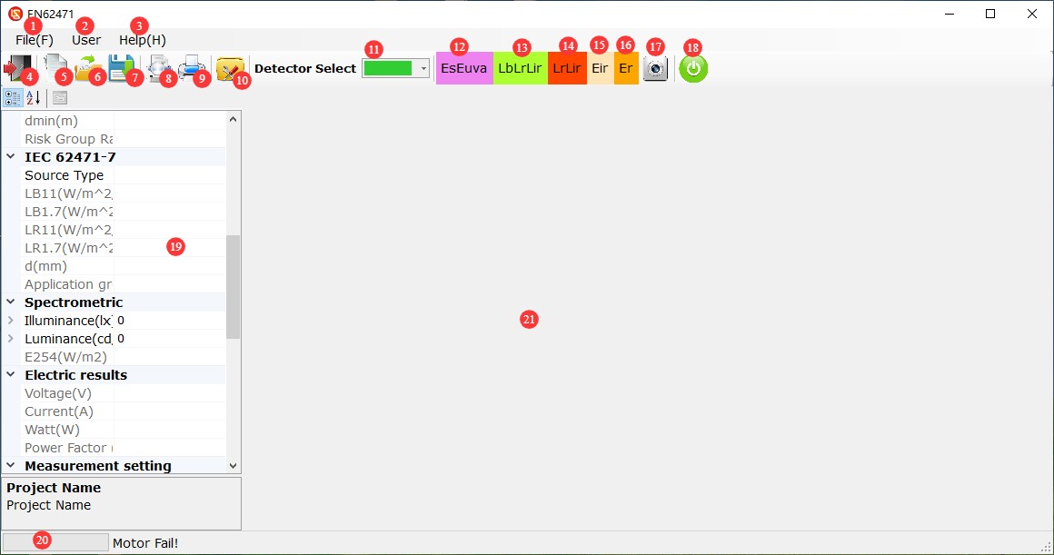
Main Screen:
| Number | Note |
| ① | File: New Test Project, Open Existing Test Project, Save Current Test Project, Print Preview, Print, Exit |
| ② | Users: Operator (required for test operations), Administrator (used for standard lamp calibration; password is 888888), Engineer (used by LISUN when debugging equipment) |
| ③ | Help: Print Report Settings, About Us |
| ④ | Exit the Software |
| ⑤ | Create a New Test Project: You must create a new test project before measuring each new sample; the test results will be saved in the corresponding project folder. |
| ⑥ | Open a Saved Test Project |
| ⑦ | Save Test Case: Save changes to the current test case |
| ⑧ | Test Report Print Preview |
| ⑨ | Print Test Report |
| ⑩ | System Settings |
| ⑪ | Probe Switching. Note: Each time you switch probes, you must wait for the probe to move into position before continuing. |
| ⑫ | EsEuva Spectral Test Button: When the probe is switched to EsEuva, click this button to switch to the EsEuva spectral test interface (200–800 nm or 200–850 nm) to measure parameters such as illuminance, ultraviolet irradiance, and near-infrared irradiance. |
| ⑬ | LbLrLir Spectral Test Button: When the probe is switched to LbLrLir mode, click this button to switch to the LbLrLir spectral test interface (300–800 nm or 300–1050 nm) to measure parameters such as luminous intensity and retinal effective radiant intensity. |
| ⑭ | LrLir Spectral Test Button: When the probe is switched to LbLrLir mode, tap the LrLir Spectral Test button to enter the LrLir spectral test interface and measure spectral radiance. This will provide measurement results for Lr (1050–1400 nm) and Lir (1050–1400 nm). |
| ⑮ | Eir Irradiance Test Button: When the probe is switched to Eir mode, click this button to switch to the Eir irradiance test interface and measure effective irradiance in the 780–3000 nm range. |
| ⑯ | Er Spectrum Test Button: When the probe is switched to Er mode, click the Er Spectrum Test button to enter the Er spectrum test interface and measure the effective irradiance and spectrum from 850 to 1550 nm. |
| ⑰ | Retinal Luminance Distribution Test Button: When the probe is switched to LbLrLir, click this button to enter the phto-luminance meter measurement interface, where you can measure the apparent luminance of a light source, the luminance of a small light source, and the maximum effective radiant luminance at different fields of view. |
| ⑱ | Power and Power Meter Buttons: Opens the power and power meter control window to manage power and communication power meter data |
| ⑲ | Test Results Section |
| ⑳ | Current Status of the Software |
| ㉑ | Probe Test Interface Display Area |
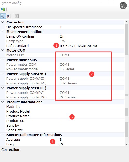
4.1 System Settings Screen
| No. | Note |
| ① Select a reference standard | IEC 62471/EN 62471/62778/IEC 62471-7/IEC 62471-5/GB/T 30117.1-2024 (divided into unintentional and intentional observation) |
| ② All device communication ports | Automatic recognition—no modifications required |
| ③ Product Information | You can enter the product model, name, etc. |
| ④ Spectral Acquisition Parameters | Currently supports DC (flicker-free), 50 Hz, 60 Hz, 100 Hz, and 120 Hz. Please note that when set to anything other than DC, auto exposure is enabled by default: Set to DC for steady light; set to 50 Hz for 50 Hz AC strobe; set to 60 Hz for 60 Hz AC strobe; For 100 Hz AC stroboscopic lighting, set it to 100 Hz or 50 Hz; for 120 Hz AC stroboscopic lighting, set it to 120 Hz or 60 Hz; |
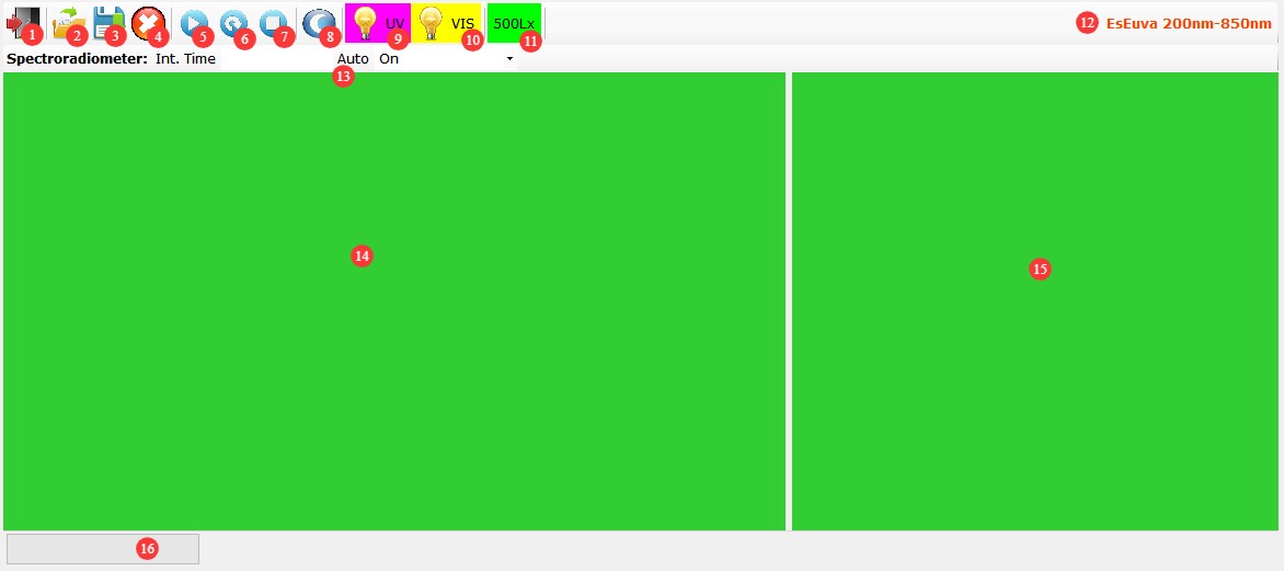
4.2 EsEuva Spectral Testing Interface
| Number | Note |
| ① | Close the EsEuva Spectral Testing Interface |
| ② | Open an existing data file |
| ③ | Save the current data file |
| ④ | Clear Display |
| ⑤ | Single Collection |
| ⑥ | Continuous Collection |
| ⑦ | Stop Collection |
| ⑧ | Measuring Dark Current |
| ⑨ | UV Calibration |
| ⑩ | Visible-Near-Infrared Calibration |
| ⑪ | Increase the illuminance reading to make it easier to move the sample being tested to the 500 lx mark. |
| ⑫ | Wavelength range tested on this test interface |
| ⑬ | For the points accumulation time setting, “Auto” is generally the best choice. |
| ⑭ | Spectrum Display Area |
| ⑮ | Key Parameter Display Area |
| ⑯ | Test status display; after the test is complete, the path where the test results file is automatically saved is displayed. |
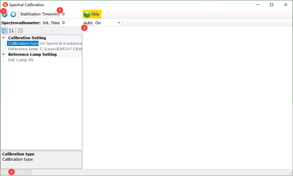
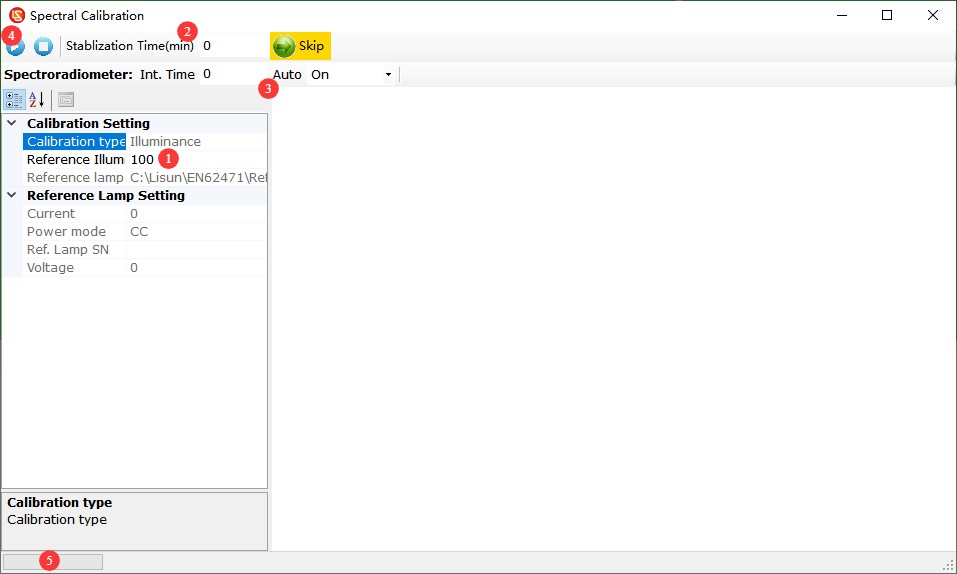
4.2.1 UV Calibration Interface
| Number | Note |
| ① | Preheat Function |
| ② | For the points accumulation time, you can usually just select “Automatic.” |
| ③ | Click here to perform UV calibration |
| ④ | Calibration Status Display |
| Note: No changes are needed to the other settings. | |
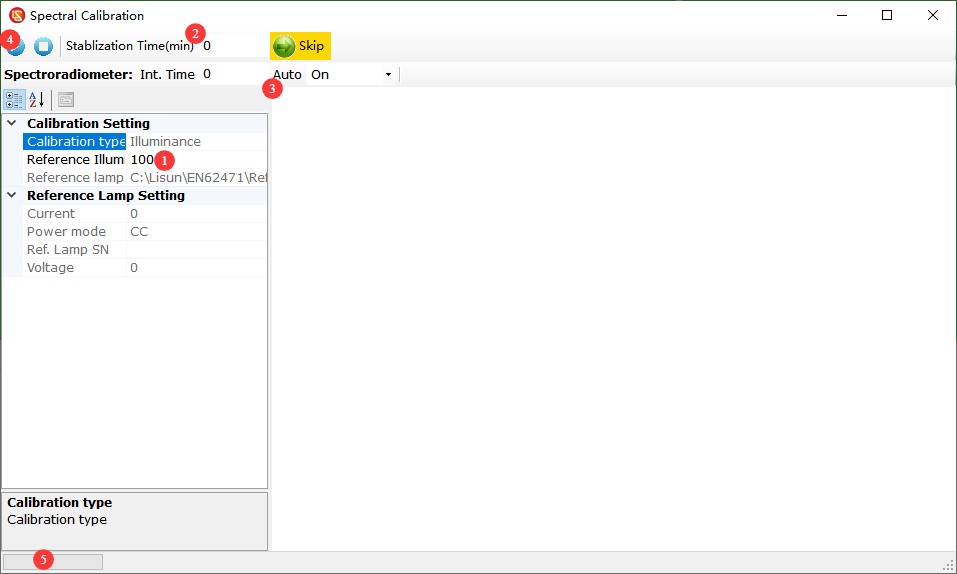
4.2.2 Visible-Near-Infrared Calibration Interface
| Number | Note |
| ① | Enter the standard illuminance value in lx |
| ② | Preheat Function |
| ③ | For the “Earn Points” feature, you can usually just select “Auto.” |
| ④ | Click here to perform UV calibration |
| ⑤ | Calibration Status Display |
| Note: No changes are needed to the other settings. | |
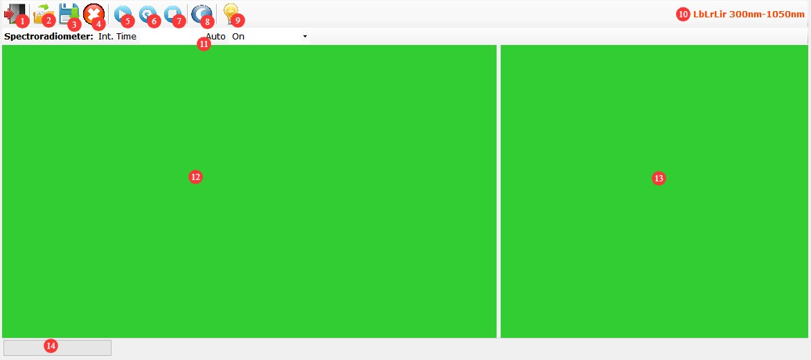
4.3 LbLrLir Spectral Testing Interface
| Number | Note |
| ① | Close the LbLrLir Spectral Test Interface |
| ② | Open an existing data file |
| ③ | Save the current data file |
| ④ | Clear Display |
| ⑤ | Single Collection |
| ⑥ | Continuous Collection |
| ⑦ | Stop Collection |
| ⑧ | Measuring Dark Current |
| ⑨ | LbLrLir Spectral Calibration |
| ⑩ | Wavelength range tested by this test interface |
| ⑪ | For the points accumulation interval setting, “Automatic” is usually the best choice. |
| ⑫ | Spectrum Display Area |
| ⑬ | Key Parameter Display Area |
| ⑭ | Test status display; after the test is complete, the path where the test results file is automatically saved is displayed. |
4.3.1 LbLrLir Spectral Calibration Interface
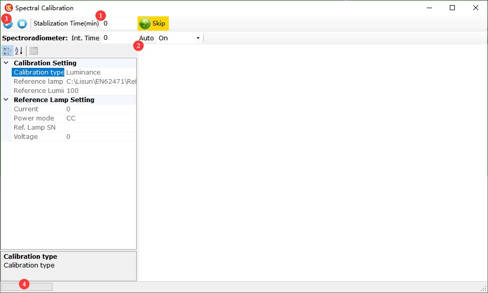
| Number | Note |
| ① | Preheat Function |
| ② | For the “Points Time” setting, you can usually just select “Auto.” |
| ③ | Click to calibrate |
| ④ | Calibration Status Display |
| Note: No changes are needed to the other settings. | |
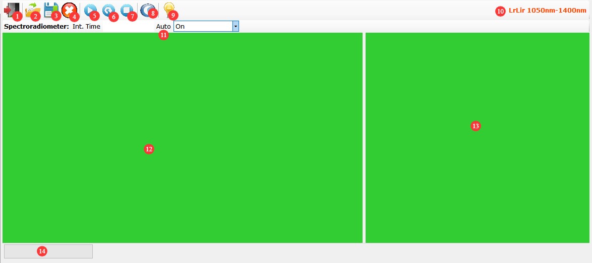
4.4 LrLir Spectral Testing Interface
| Number | Note |
| ① | Close the LrLir Spectral Test Interface |
| ② | Open an existing data file |
| ③ | Save the current data file |
| ④ | Clear Display |
| ⑤ | Single Collection |
| ⑥ | Continuous Collection |
| ⑦ | Stop Collection |
| ⑧ | Measuring Dark Current |
| ⑨ | LrLir Spectral Calibration |
| ⑩ | Wavelength range tested on this test interface |
| ⑪ | For the points accumulation time setting, “Automatic” is usually the best choice. |
| ⑫ | Spectrum Display Area |
| ⑬ | Key Parameter Display Area |
| ⑭ | Test status display; after the test is complete, the path where the test results file is automatically saved is displayed. |
4.4.1 LrLir Spectral Calibration Interface
| Number | Note |
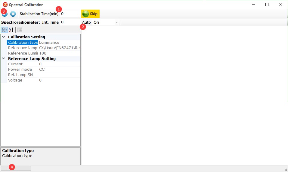
| ① | Preheat Function |
| ② | For the “Accumulation Time” setting, you can usually just select “Auto.” |
| ③ | Click to calibrate |
| ④ | Calibration Status Display |
| Note: No changes are needed to the other settings. | |
4.5 Eir Irradiance Test Interface
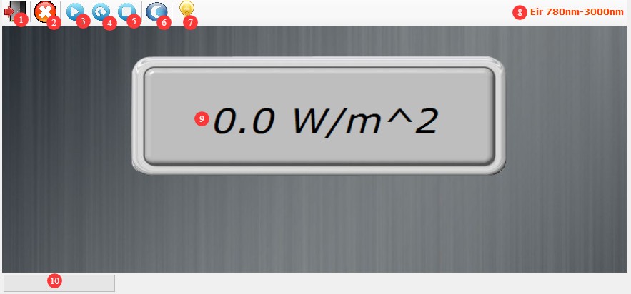
| Number | Note |
| ① | Close the Eir Irradiance Test Interface |
| ② | Clear Display |
| ③ | Single Collection |
| ④ | Continuous Collection |
| ⑤ | Stop Collection |
| ⑥ | Measuring Dark Current |
| ⑦ | Eir Irradiance Calibration |
| ⑧ | Wavelength range tested on this test interface |
| ⑨ | The test results show that |
| ⑩ | Test Status Display |
4.5.1 Eir Irradiance Calibration Interface
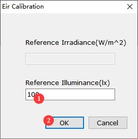
| Number | Note |
| ① | Enter the standard illuminance value in lx |
| ② | Click OK to complete the calibration. |
4.6 Er Spectral Test Interface
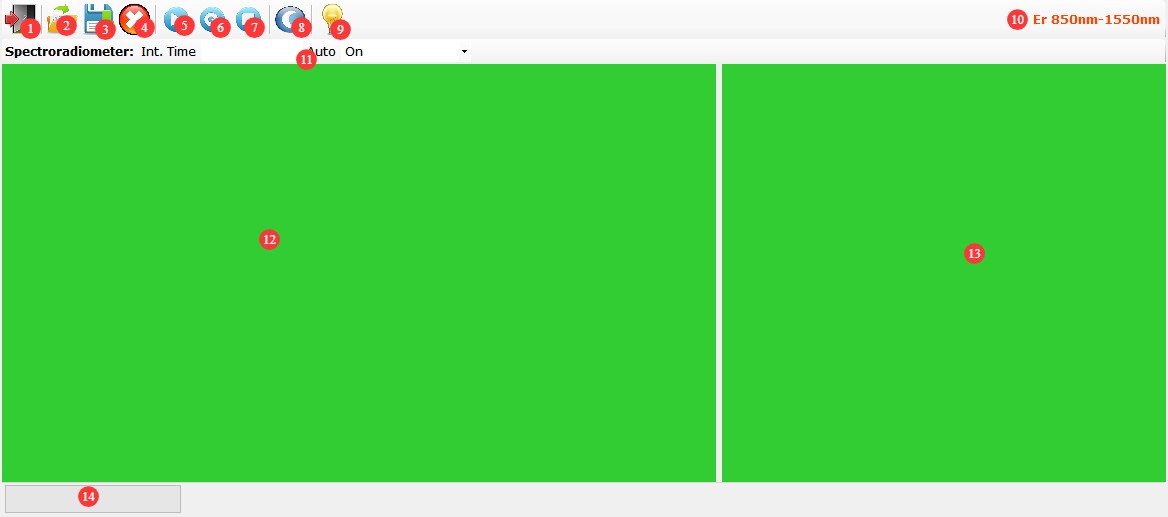
| Number | Note |
| ① | Close the Er Spectrum Test Interface |
| ② | Open an existing data file |
| ③ | Save the current data file |
| ④ | Clear Display |
| ⑤ | Single Collection |
| ⑥ | Continuous Collection |
| ⑦ | Stop Collection |
| ⑧ | Measuring Dark Current |
| ⑨ | Er Spectral Calibration |
| ⑩ | Wavelength range tested on this test interface |
| ⑪ | For the points accumulation time setting, “Automatic” is usually the best choice. |
| ⑫ | Spectrum Display Area |
| ⑬ | Key Parameter Display Area |
| ⑭ | Test status display; after the test is complete, the path where the test results file is automatically saved is displayed. |
4.6.1 Er Spectrum Calibration Interface
| Number | Note |
| ① | Enter the standard illuminance value in lx |
| ② | Preheat Function |
| ③ | For the “Earn Points” feature, you can usually just select “Auto.” |
| ④ | Click to calibrate |
| ⑤ | Calibration Status Display |
| Note: No changes are needed to the other settings. | |
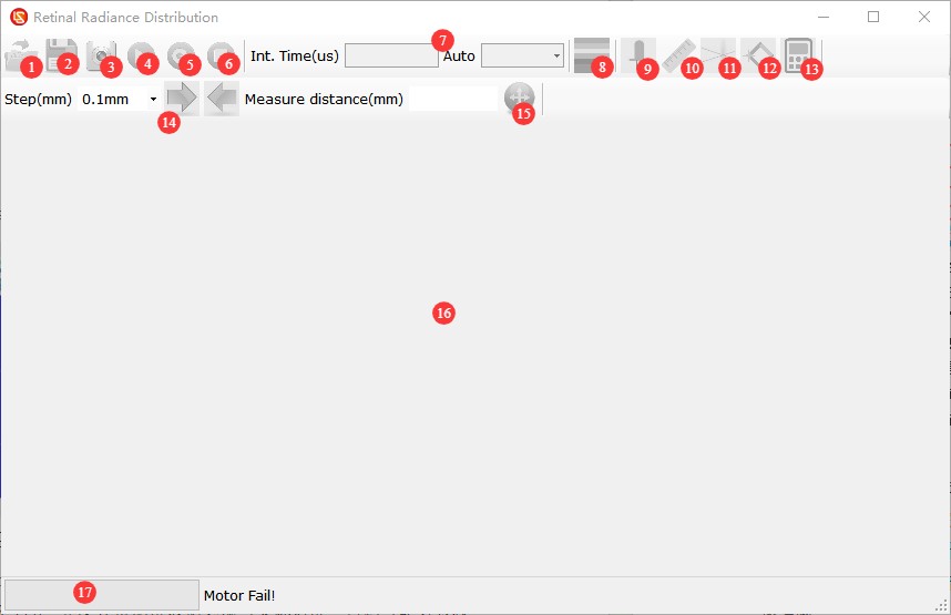
4.7 Retinal Luminance Distribution Test Interface
| Number | Note |
| ① | Open an existing data file |
| ② | Save the current data file |
| ③ | Start the luminance meter |
| ④ | Single Collection |
| ⑤ | Continuous Collection |
| ⑥ | Stop Collection |
| ⑦ | Integration Time Settings: On this screen, we recommend using manual integration time. |
| ⑧ | Pseudo-color display |
| ⑨ | Apparent Light Source Display |
| ⑩ | Ruler |
| ⑪ | Measurement of the apparent solid angle of a light source; the light source is a rectangle |
| ⑫ | Measurement of the apparent solid angle of a light source; the light source is an oblique rectangle |
| ⑬ | Evaluation of Luminance Distribution |
| ⑭ | Stepping Fine-Tuning Test Distance |
| ⑮ | Enter the test distance directly and confirm |
| ⑯ | Test Display Area |
| ⑰ | Test status display; after the test is complete, the path where the test results file is automatically saved is displayed. |
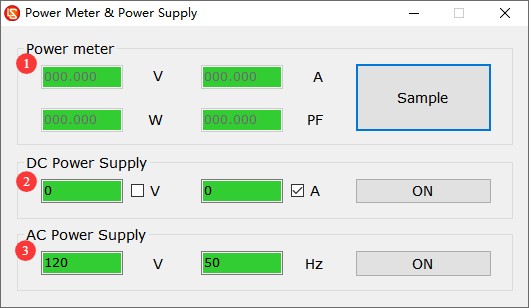
4.8 Power Supply and Power Meter Interface
| Number | Note |
| ① | Power Meter Control Module: Click “Sample” to retrieve the current electrical parameter data from the power meter. |
| ② | DC Power Control Module: Check “V” for constant-voltage output, or check “A” for constant-current output. Enter the appropriate voltage and current values, then click ON/OFF to control the output . Note: The standard model is DC3005, which has a maximum output voltage of 30V and a maximum output current of 5A. |
| ③ | AC Power Control Module: Set the input voltage and frequency, then click ON/OFF to control the output |
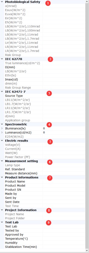
4.9 Test Results Display Area
| Number | Note |
| ① Photobiological Safety Parameters | Displays test results for parameters related to CIE S009/IEC 62471/GB/T 20145, EN 62471, IEC 62471-5, and GB/T 30117.1-2024. α: Apparent light source angle; must be measured; Esuv: Effective irradiance for photochemical UV hazard, applicable only to test specimens containing UV spectral components; Euva: Effective irradiance for near-UV hazard, applicable only to test specimens containing UV spectral components; EB: Effective irradiance for blue light hazard, corresponding to 11 mrad; Eir: Effective irradiance for thermal hazard to the eye; applies only to test specimens containing infrared spectral components; EH: Effective irradiance for thermal hazard to the skin; LB: Effective luminance for blue light hazard; Lir: Effective luminance for retinal thermal hazard due to faint visual stimulation; LR: Effective radiance for retinal thermal hazard; Light Safety Class: The safety class of the tested sample is determined based on IEC 62471/GB/T 20145, EN 62471, IEC 62471-5, and GB/T 30117.1-2024. |
| ② IEC 62778 Blue Light Hazard Parameters | True Luminance: The luminance at the brightest point of the test specimen, with a field of view of 1.7 mrad; D: Size of the light-emitting surface of the small light source; LB: Effective radiance of blue light hazard; Ethr: Critical illuminance, safety illuminance limit; Imax: Maximum measured luminous intensity; dmin: Safe distance; Visible light safety class range: The visible light safety class of the tested sample is determined in accordance with IEC 62778 |
| ③IEC 62471-7 Blue Light Hazard Parameters | Source Type: Type of sample under test; LB11: Effective radiance for retinal blue light hazard (11 mrad field of view); LB1.7: Effective radiance for retinal blue light hazard (1.7 mrad field of view); LR11: Effective radiance for retinal thermal hazard (11 mrad field of view); LR1.7: Effective radiance for retinal thermal hazard (1.7 mrad field of view); d: Distance at which the effective radiance for retinal blue light hazard (11 mrad field of view) and the effective radiance for retinal thermal hazard (11 mrad field of view) are below the limit values (actual testing is recommended; the value shown here is an approximation calculated by the software); Application group: Classification |
| ④ Spectral Parameters | Displays the main spectral test results, including illuminance, luminance, color coordinates, and color temperature |
| ⑤ Electrical Parameters | Voltage, Current, Power, Power Factor |
| ⑥ Test Parameters | Light Source Types, Reference Standards, Test Distance |
| ⑦ Information on the Test Sample | |
| ⑧ Test Item Information | |
| ⑨Testing Laboratory Information | |
5. System Calibration
5.1 Introduction to Standard Lamps and Accessories
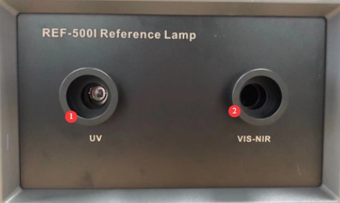
5.1.1 Ultraviolet Standard Lamps and Visible-Near-Infrared Standard Lamps
| Number | Note |
| ① | Light-emitting aperture of the UV standard lamp |
| ② | The light-emitting aperture of the near-infrared standard lamp is visible |
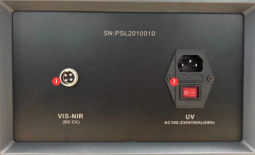
| Number | Note |
| ① | As shown, the near-infrared standard lamp has a power jack that requires a DC power supply and comes with a dedicated power cord. |
| ② | The power cord receptacle and power switch for the UV standard lamp require an AC power supply. |
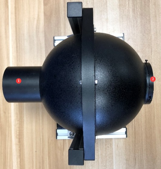
5.1.2 Standard Luminance Lamp
| Number | Note |
| ① | The power supply side of the standard luminance lamp requires a DC power supply and is equipped with a dedicated power cable. |
| ② | Light-emitting aperture of the standard luminance lamp |
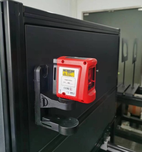
5.1.3 Support Tools
Horizontal cross-line laser. It attaches to the optical testing unit via a magnetic mount, and the horizontal laser can be used to verify that the probe and the light-emitting aperture of the standard lamp are on the same horizontal line.
Adjustable mount: Place a standard lamp on the adjustable mount, then place the mount on the optical rail. This makes it easy to adjust the distance and height of the standard lamp.
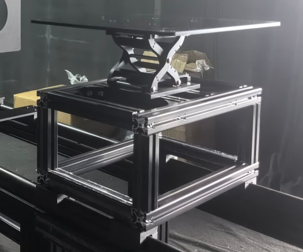
5.2 Measuring Dark Current
Turn off all lights in the darkroom and use a light-blocking cap to cover the probe test hole.
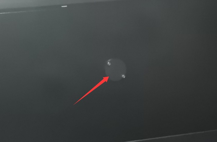
Then, following the instructions in sections 4.2, 4.3, 4.4, 4.5, and 4.6, click the dark current acquisition icon on all screens. Once all data has been successfully acquired, remove the light shield and prepare for calibration.
Note: Dark current must be measured before each calibration; it is also recommended to measure dark current before each test.
5.3 Calibration Procedure
Note: If the system is used frequently, it is recommended to calibrate it once every 3 months; if the system has not been used for an extended period, it must be calibrated before the next use.
5.3.1 Calibration of UV Standard Lamps
| Instructions | Note |
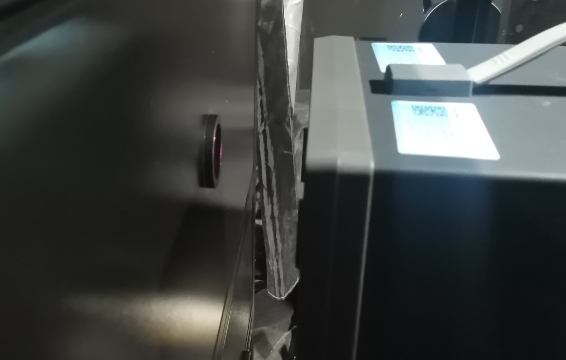
| ① | Place the UV standard lamp on the lifting stand so that the light-emitting aperture of the UV standard lamp is directly aligned with the probe test aperture on the optical main unit, and the light-emitting aperture is 100 mm away from the probe test aperture. |
| ② | Connect the power cord of the UV standard lamp to the mains power supply and turn it on, then ensure that there is no other lighting in the darkroom and that no light is leaking in. |
| ③ | The UV standard lamp requires a 10-minute warm-up period; wait until it has stabilized before calibrating it. |
| ④ | In the software interface, switch the probe to EsEuva, enter the EsEuva spectral test interface, and perform calibration as described in Section 4.2.1. Once calibration is complete, simply close the calibration page. |
| ⑤ | Then turn off the UV standard lamp and unplug the power cord. |
Schematic Diagram of UV Standard Lamp Installation and Placement:
5.3.2 Calibration Using Visible and Near-Infrared Standard Lamps
| Instructions | Note |
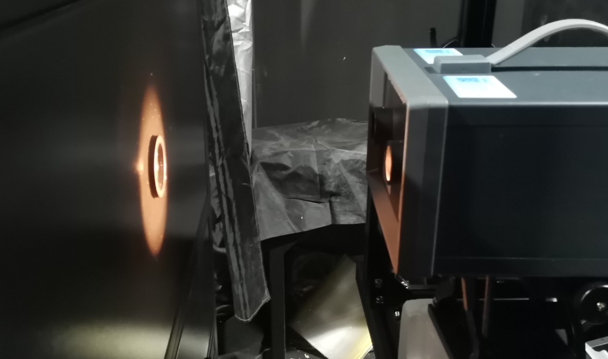
| ① | Place the visible near-infrared standard lamp on the adjustable stand so that the light-emitting aperture is directly aligned with the probe test port on the optical main unit, and the distance between the light-emitting aperture and the probe test port is 137 mm. |
| ② | Connect the unit to the sample mount using the dedicated power cord. Set the AC/DC switch on the cabinet to DC. Refer to Section 4.8 to control the DC power supply: set the input to 30 V, 4 A, check box A, and click “ON” to enable 4 A constant-current output and turn on the standard lamp. Ensure there is no other lighting in the darkroom and that there is no light leakage. |
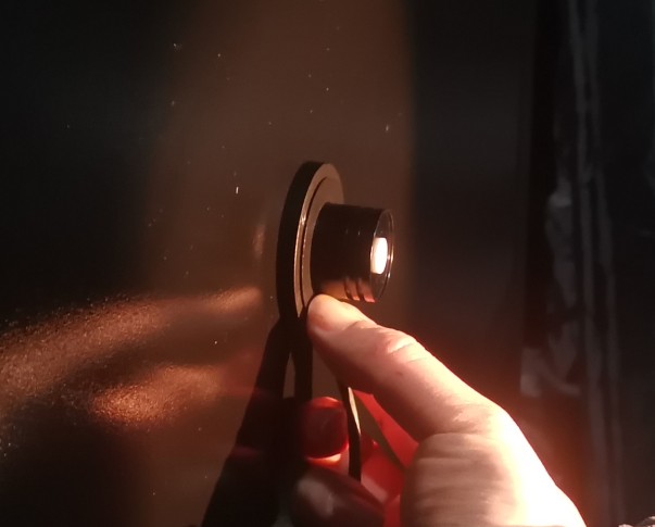
| ③ | Note that the near-infrared standard lamp must be preheated for 10 minutes, after which an accurate illuminance value should be measured using a probe adapter plate and a Pocket Illuminance Meter (Note: The Pocket Illuminance Meter automatically switches between illuminance units of lx and klx; 1 klx = 1000 lx—please verify this). |
| ④ | Then remove the probe adapter plate and the Pocket Illuminance Meter, and position the light-emitting aperture of the standard lamp 200 mm away from the probe’s test aperture (the combined thickness of the probe adapter plate and the probe of the Pocket Illuminance Meter is 37 mm). |
| ⑤ | In the software interface, the probe is still set to EsEuva. Go to the EsEuva spectral test interface (see Section 4.2.2). No additional warm-up is required. Enter the standard illuminance value to perform calibration. Once calibration is complete, simply close the calibration page. |
| ⑥ | In the software interface, switch the probe to Eir, enter the Eir irradiance test screen, refer to Section 4.5.1, enter the standard illuminance value, and perform calibration. Once calibration is complete, simply close the calibration page. |
| ⑦ | In the software interface, switch the probe to Er and enter the Er spectral test interface (see Section 4.6.1). No additional warm-up is required. Enter the standard illuminance value to perform calibration. Once calibration is complete, simply close the calibration page. |
| ⑧ | Once you have finished using the near-infrared standard lamp, refer to Section 4.8 to turn off the DC power output, unplug the standard lamp’s power cord, and store the UV-Vis-NIR standard lamp properly. |
See the installation and placement diagram for the near-infrared standard lamp:
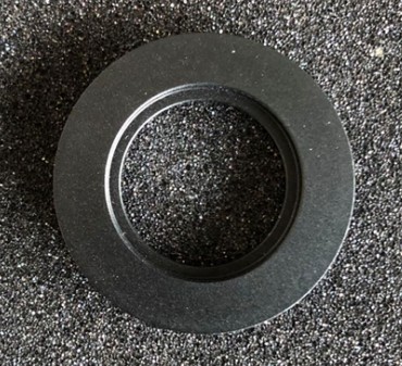
Probe Adapter Board:
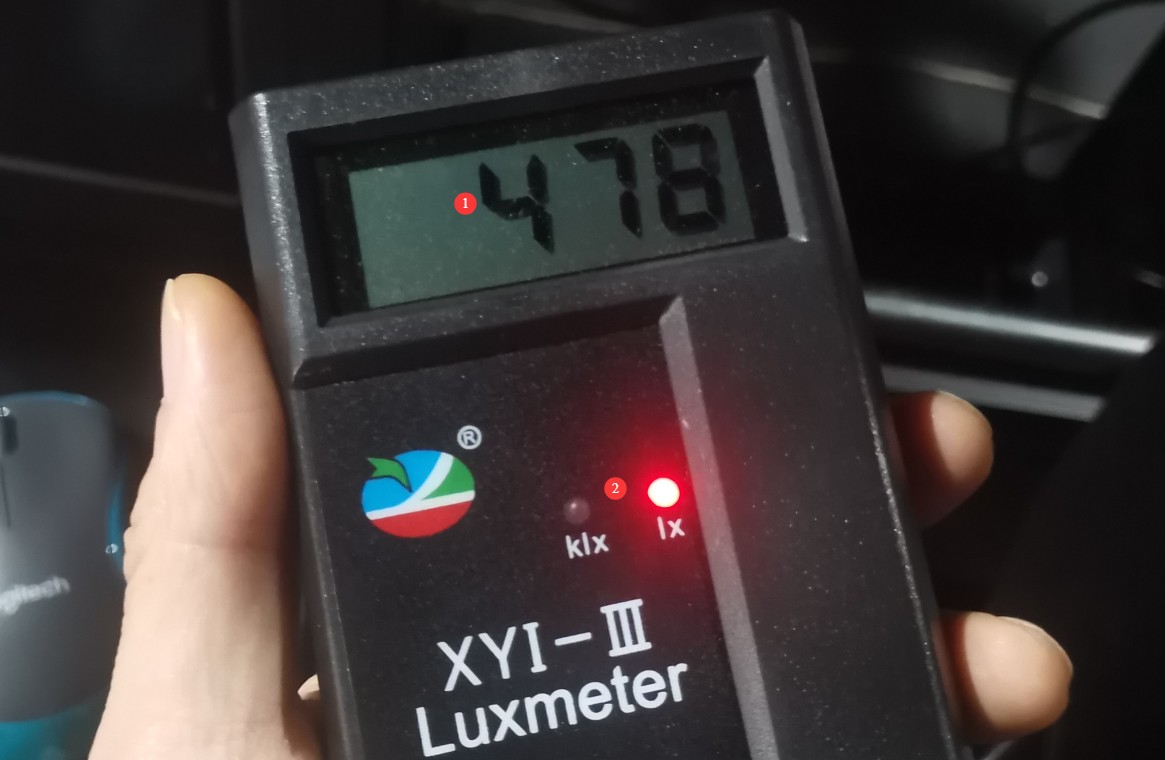
Schematic diagram of a Pocket Illuminance Meter display and unit indicator lights:
| Number | Note |
| ① | Digital Display of Standard Illuminance Values |
| ② | Note the current unit; if the “klx” indicator is lit, multiply the value by 1000. |
5.3.3 Calibration Using a Standard Luminance Lamp
| Instructions | Note |
| ① | Place the standard luminance lamp on the adjustable stand so that the light-emitting aperture is directly aligned with the probe test aperture on the optical main unit, and the light-emitting aperture is 200 mm away from the probe test aperture. |
| ② | Connect the unit to the sample mount using the dedicated power cord. Set the AC/DC switch on the cabinet to DC. Refer to Section 4.8 to control the DC power supply: set the input power supply to 30 V, 4 A; check box A; click “ON” to enable a constant current output of 4 A and turn on the standard lamp. Ensure there is no other lighting in the darkroom and that there is no light leakage. |
| ③ | The standard luminance lamp must be allowed to warm up for 10 minutes; calibration should be performed only after it has stabilized. |
| ④ | In the software interface, switch the probe to LbLrLir. First, go to the retinal distribution test screen (see Section 4.7), adjust the test distance to 200 mm, start the luminance meter, and try setting different manual integration times to collect data. Ensure that the aperture of the standard luminance source on the display screen aligns with the center of the green circle.and the image is clear. Check the test status section to ensure the signal level is above 70% and does not overflow (if the signal is too strong, shorten the integration time; if the signal is too weak, increase the integration time). |
| ⑤ | Open the LbLrLir spectral test interface, perform calibration as described in Section 4.3.1, and close the calibration page once calibration is complete. |
| ⑥ | Open the LrLir spectral test interface, perform calibration as described in Section 4.4.1, and close the calibration page once calibration is complete. |
| ⑦ | After using the luminance standard lamp, refer to Section 4.8 to turn off the DC power output, unplug the standard lamp’s power cord, and store the luminance standard lamp properly. |
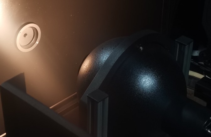
Installation and Placement Diagram for Standard Luminance Lamps:
6. Testing
6.1 Preparations Before Testing
6.1.1 Measuring Dark Current
Measure the dark current according to Section 5.2.
6.1.2 Determining the Measurement Distance
IEC 62471-7: Measurements are taken at a distance of 200 mm or 1000 mm, depending on the application; IEC 62471-5: 1000 mm measurement distance.
If specific product standards specify classification or measurement requirements, those requirements take precedence: In IEC 62471:2006, lamps and lighting systems for general lighting are evaluated using the location where an illuminance of 500 lx is produced as the assessment distance for classification; for example, for products such as stadium lighting fixtures, stage spotlights, and automotive headlights, the assessment distance for classification is 1 m.
6.1.3 Determining the Measurement Wavelength Range
For example, since the spectral range of LED lighting falls within the visible light spectrum, it is sufficient to measure only the EsEuva spectrum, the LbLrLir spectrum, and the retinal luminance distribution. Of course, you can also perform all the test items.
6.1.4 Install and illuminate the test specimen
Place the test sample in the center of the fixture, with the light-emitting surface facing the probe’s test aperture. Connect the power cord to the sample mounting platform. Depending on the test sample’s power supply, switch the AC/DC selector switch on the cabinet, then illuminate the test sample as described in Section 4.8. Wait until the test sample reaches a stable state before proceeding with the test.
6.1.5 Adjusting the Test Distance
Adjust the test distance in accordance with the standard requirements. If the test specimen is an LED light source and is to be measured in accordance with IEC 62471-1, the measurement distance should be at an illuminance of 500 lx (not less than 200 mm).
In the software interface, switch the probe to EsEuva, click to enter the EsEuva spectral test interface (see Section 4.2), click “Continuous Acquisition,” click the 500 lx button to make the illuminance value easier to read, and move the sample stage so that the software interface displays an illuminance value of 500 lx.
6.2 Test Procedure
| Instructions | Note |
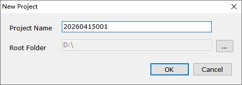
| ① | Create a new test project, enter the test project name, select a save location, and then confirm. |
| Procedure | Note |
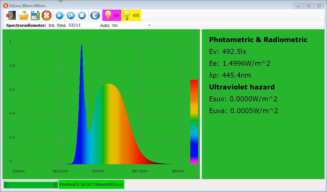
| ② | In the software interface, switch the probe to EsEuva, click to enter the EsEuva spectral test interface, refer to Section 4.2, and click “Single Acquisition” or “Continuous Acquisition” to begin testing. If using continuous acquisition, click “Stop Acquisition” after the acquisition is complete; the test results file will be saved automatically. |
| Instructions | Note |
| ③ | Switch the probe to LbLrLir, click to enter the retinal luminance distribution test interface, refer to Section 4.7, enter the actual test distance of the light source into the software, and click “Confirm.” Click “Start Luminance Meter,” then click “Continuous Acquisition.” Manually adjust the integration time to ensure that the light source area on the display roughly aligns with the center of the green circle. Ensure the image is clear. Check the test status section to ensure the signal level is above 70% and does not overflow (if the signal is too strong, shorten the integration time; if the signal is too weak, increase the integration time). If the signal continues to overflow, install the filter into the probe’s test port and try again. |
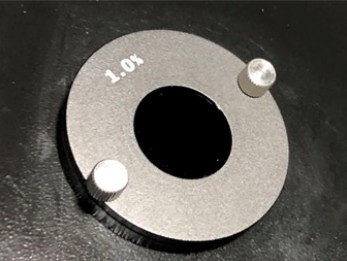
Filters and Filter Installation Results:
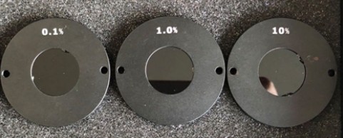
Note: Use the 10% filter first; if the test cannot be completed, continue by switching to the 1% filter.
| Instructions | Note |
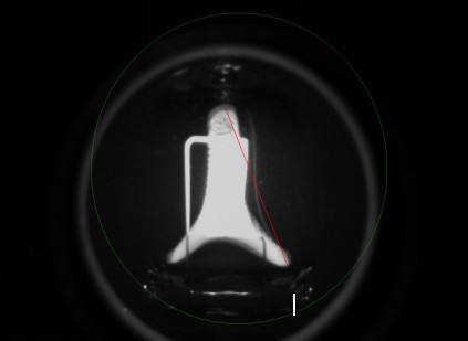
| ④ | Click on the ruler, press the left mouse button at the starting point of the measurement, drag to the end point, and release the left mouse button. The apparent light source size has been successfully measured, as shown by the red line in the figure below. |
| Instructions | Note |
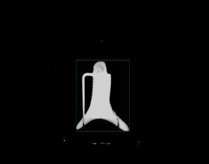
| ⑤ | Click “Show Apparent Light Sources” to have the interface display only the apparent light source areas. |
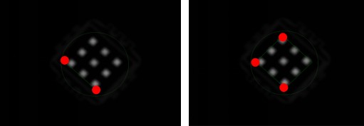
| ⑥ | Depending on the shape of the light source—whether it is a vertical rectangle or a diagonal rectangle—click the corresponding button to measure the apparent light source angle. |
If the shape is a rectangle, click and drag the left mouse button from the starting point to the ending point, then release the left mouse button. The apparent light source angle test is now complete.
If the shape is a diagonal rectangle, first select two points on one side of the light source’s edge by clicking with the mouse, then select a point on the other side of the light source’s edge by clicking once with the mouse to create a diagonal rectangular selection area.
| Instructions | Note |
| ⑦ | Then click “Brightness Distribution Evaluation.” The evaluation will take approximately 5 to 10 seconds to complete, and the test results file will be saved automatically. If you are using a filter, please remove it; filters may only be used on the retinal brightness distribution test screen. |
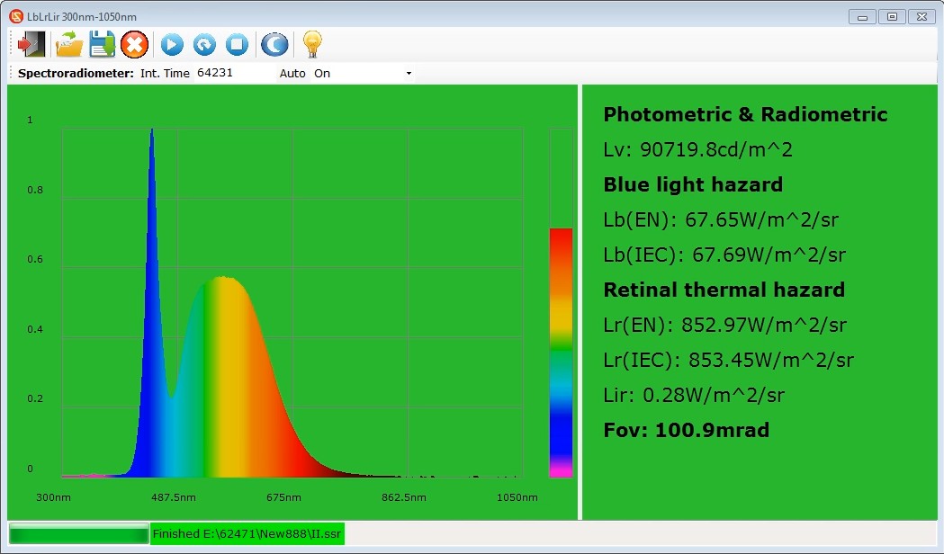
| ⑧ | Click to open the LbLrLir spectrum test interface, then click “Single Acquisition” or “Continuous Acquisition” to begin the test. If you select “Continuous Acquisition,” you must click “Stop Acquisition” once the acquisition is complete; the test results file will be saved automatically. |
| Instructions | Note |
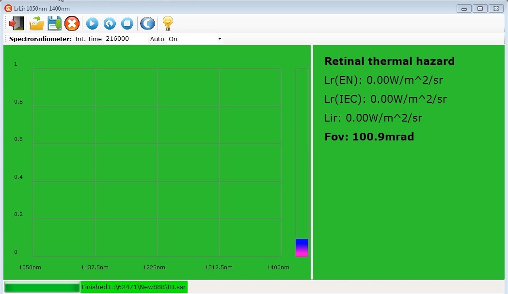
| ⑨ | Click to open the LrLir spectral test interface, then click “Single Acquisition” or “Continuous Acquisition” to begin the test. If you select “Continuous Acquisition,” you must click “Stop Acquisition” once the acquisition is complete; the test results file will be saved automatically. |
| Instructions | Note |
| ⑩ | Switch the probe to Eir, tap to open the Eir irradiance test interface, and tap “Single Measurement” or “Continuous Measurement” to begin the test. If you select “Continuous Measurement,” you must tap “Stop Measurement” once the measurement is complete; the test results file will be saved automatically. |
| ⑪ | Switch the probe to Er, click to enter the Er spectrum test interface, and click “Single Acquisition” or “Continuous Acquisition” to begin the test. If you select “Continuous Acquisition,” you must click “Stop Acquisition” after the acquisition is complete; the test results file will be saved automatically. |
| ⑫ | Refer to Section 4.8 and click on the electrical parameters of the communication power meter to display them in the test report. |
6.3 End of Testing
6.3.1 Preparation of Test Samples
Disconnect the power supply from the test sample, and remove it after it has cooled.
6.3.2 Printing the Test Report
Refer to Section 4.9, enter the relevant information, and select the reference standard. Refer to Chapter 4, access the print report settings, select the items you want to print, and then print the corresponding test report.
6.3.3 Shutdown
After the test is completed that day, shut down the system as described in Section 3.2.6 and seal the probe test port with a dust cover to prevent dust from entering.
7. Daily Maintenance and Care of Equipment
7.1 Routine Maintenance
Keep the darkroom control room clean and dust-free to prevent dust from entering the equipment. If there is dust on the surface of the equipment, wipe it off with a dry, soft cloth.
Avoid exposing the darkroom to high humidity for extended periods; keep a dehumidifier on hand if necessary.
7.2 Long-Term Decommissioning and Maintenance
7.2.1 Equipment Cleaning and Protection
Thoroughly clean all equipment surfaces, and cover the optical test unit, optical guide rails, and cabinet with dust-proof cloths.
7.2.2 Environmental Protection
Ensure that the darkroom is dry and well-ventilated to prevent equipment from becoming damp. If the ambient humidity is high, keep a dehumidifier on hand.
7.2.3 Monthly Power-On
Conduct a power-on test once a month to ensure that all system hardware is functioning properly.
8. Troubleshooting and Resolving Common Problems
| Fault Symptoms | Possible Causes | Procedure |
| Abnormal calibration or test data | Probe not switched | The optical test unit includes multiple probes; before testing, make sure to switch to the correct probe. |
| Eir, Er, LrLir: No data found for these tests | The sample being tested does not emit infrared light. | Conventional lighting has an extremely weak infrared component, so the device may not display any data; use a halogen or incandescent light bulb to verify the infrared testing function. |
| LbLrLir, LrLir—the test interface won’t open | No retinal luminance distribution test was performed beforehand | Whether you are calibrating or testing, you must first access the retinal luminance distribution test interface to perform the test correctly before proceeding to the LbLrLir and LrLir test interfaces. |
| DC Power Output Abnormality | The AC/DC switch on the cabinet has not been switched to DC; the sample voltage and current exceed the DC power supply limits; the sample is short-circuited. | Please verify that the sample’s voltage and current are within the DC power supply’s output range. For example, the DC3005 model has a maximum output voltage of 30 V and a maximum output current of 5 A. Check whether the sample is short-circuited; if so, repair the sample before retesting. |
| AC Power Output Abnormality | The AC/DC switch in the cabinet has not been switched to the AC side; the overload protection has been triggered. | Check the AC power output wiring and sample connections to ensure there are no loose connections or short circuits; if the overload protection is triggered, turn off the power, let the unit cool for 5 minutes, and then restart it. Ensure that the sample power remains within the AC power output range; for example, the LSP-500VARC has a maximum output power of 500W. |
9. Packing List
| No. | Name | Quantity |
| ① | Optical Test System | 1 unit |
| ② | Optical Guide Rails | 1 set |
| ③ | Cabinet | 1 |
| ④ | Industrial Computer | 1 set |
| ⑤ | Sample Mounting Stand | 1 |
| ⑥ | Fixture | |
| ⑦ | Cross-Line Laser | |
| ⑧ | Light-blocking cover | |
| ⑨ | Filter | 3 |
| ⑩ | Ruler | 1 |
| ⑪ | Lifting Bracket | |
| ⑫ | Sunshade | Several |
| ⑬ | LS Series Power Meters | 1 unit |
| ⑭ | DC Series Digital CC and CV DC Power Supply | |
| ⑮ | LSP Series Pure Sine Wave AC Power Supplies | |
| ⑯ | UV-Vis-NIR Standard Lamps | 1 set |
| ⑰ | Standard Luminance Lamp | 1 |
| ⑱ | Standard Pocket Illuminance Meter | |
| ⑲ | Standard Pocket Illuminance Meter | |
| ⑳ | Probe Adapter Board |