
 English
 中文简体
中文简体 English
 Русский
 Español
 Português
 Türkçe
 العربية
 Deutsch
 Polski
 Italiano
 Français
 한국어
한국어 ไทย
ไทย Tiếng Việt
 日本語
日本語





























EMI Receiver System
User's Manual
Applicable LISUN models: EMI-9KB
1. Basic Understanding of Equipment
1.1 Product Overview
1.1.1 Scope Of Application Of the Product
The EMI-9KB Conducted and Radiated Emission Test System is a fully automated EMI pre-testing device primarily used for conducted emission voltage testing and alternative methods for radiated emission testing of electrical and electronic products. The system features a fully enclosed, highly conductive chassis design that provides excellent shielding performance and low intrinsic interference levels. Test results are presented in an internationally recognized report format, making the system widely used for EMI research, development, debugging, and pre-compliance testing of products such as lighting fixtures, household appliances, power tools, and switching power supplies.
1.1.2 Main Components of the System
| Number | Note |
| ①EMI-9KB Receiver | The core testing unit of the system, responsible for receiving, amplifying, and detecting interference signals as well as processing data. It covers a frequency range of 9 kHz to 300 MHz and supports three detection modes: peak (PK), quasi-peak (QP), and average (AV). Fully automated testing can be performed using host computer software. |
| ②LISN-C Artificial Mains Network | Used for conducted emission testing in the 9 kHz to 30 MHz frequency range. It provides high-frequency isolation between the equipment under test (EUT) and the power supply, simulates the mains impedance specified in the standard, standardizes test conditions, and simultaneously couples and extracts interference signals from the power line. |
| ③CDNE-M316 Coupling Decoupling Network | Used for radiated emission testing via the substitution method in the 30 MHz to 300 MHz frequency range; extracts the equivalent radiated emission signal of the EUT through common-mode coupling. |
| ④Isolation Transformer | There are 2 units in total. Isolation Transformer supplies power to the LISN/CDNE and the device under test, providing electrical isolation between the power grid and the test circuit and reducing background interference from the power grid; Isolation Transformer low-capacity Isolation Transformer supplies power to the EMI-9KB receiver, computer, and printer, preventing surrounding equipment from interfering with the test circuit. |
| ⑤20 dB Coaxial Attenuator | Used to attenuate high-level interference signals and protect the receiver’s input port; when using LISN-C, a coaxial attenuator may be used as needed. |
1.3 Equipment Configuration Verification
1.3.1 Unpacking
When unpacking the device, handle it gently to avoid scratching the casing with sharp tools. After unpacking, first inspect the exterior of the device to ensure there is no visible deformation or dents, and that the buttons are not damaged or loose. If you notice any abnormalities with the device or its accessories, do not turn on the power. Please contact us immediately.
1.3.2 Main Unit and Accessories
Main units: 1 EMI-9KB, 1 LISN-C, and 1 CDNE-M316; 2 Isolation Transformer.
See Figure 1-1 for other components.
| Number | Note |
| ① | 12V power adapter for connecting to the LISN-C |
| ②③ | Coaxial cable for connecting the EMI-9KB to the LISN-C or CDNE |
| ④ | Power cord for the EMI-9KB |
| ⑤ | AE and EUT connection cables, used to connect to the CDNE |
| ⑥ | Grounding copper plate, used to connect to the LISN-C grounding terminal |
| ⑦⑧ | RS-232 communication cable and RS-232-to-USB adapter cable, used to connect the EMI-9KB to a computer |
| ⑨⑩ | 10A to 16A and 16A to 10A adapter plugs for LISN-C |
| ⑪ | 20 dB Coaxial Attenuator |
| ⑫ | N-to-BNC adapter; an adapter is required when connecting to an LISN-C using coaxial cable |
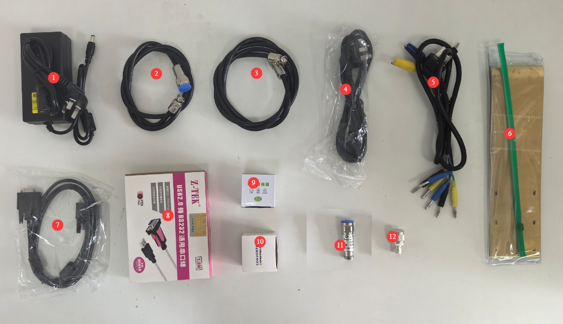
Figure 1-1
1.3.3 Downloading Electronic Documents
Links to the digital user manual, warranty card, calibration certificate, and other documents have been sent via email. If you did not receive the email, please contact us to obtain the links again.
2. Safety Precautions
2.1 Electrical Safety
2.1.1 Power Supply Safety
All equipment must be connected to Isolation Transformer via an Isolation Transformer; direct connection to the mains is strictly prohibited to prevent power surges and the risk of electric shock.
The EMI-9KB main unit must be connected to a stable single-phase AC power source rated at 220 V ±10%, 50/60 Hz; do not use the device if the power connections are loose or the power cord is damaged.
2.1.2 Grounding Safety
A separate and reliable grounding system must be installed; the lower the grounding resistance, the more accurate the test results will be. Sharing a grounding electrode with high-power electrical equipment is strictly prohibited.
The grounding terminals and reference metal plates of all equipment must be securely connected to the grounding electrode; the connection points must be free of corrosion and loose.
During thunderstorms, disconnect the equipment from both the power source and the ground to prevent damage from lightning strikes.
2.2 Operational Safety
2.2.1 Power On/Off and Connection/Disconnection Procedures
Strictly follow the sequence: “When turning on the computer, power on the peripherals first, then the main unit; when turning off the computer, power off the main unit first, then the peripherals.”
Before powering on or off the EUT, you must first disconnect the coaxial cable from the receiver’s front end to prevent switching spikes from damaging the receiver’s internal circuitry.
Do not connect or disconnect coaxial cables or toggle the L/N phase switch on the LISN during test operation, as high-voltage pulses may damage the receiver’s RF input module.
2.2.2 Input Signal Limits
Receiver RF input port: For LISN-C high-level interference testing, if the signal level exceeds 70 dBuV, an attenuator meeting the corresponding specifications must be connected in series.
The load current for the LISN and CDNE must not exceed the maximum rated value of 16 A; overloading may cause the equipment to burn out.
2.3 Environmental Safety
2.3.1 Work Environment Requirements
The equipment’s operating environment temperature is 5–35°C, with a relative humidity of ≤80% and no condensation.
It is strictly prohibited to store flammable, explosive, or corrosive materials within the test area, and it is strictly prohibited to conduct powered tests in flammable or explosive environments.
Equipment that generates strong electromagnetic interference—such as variable-frequency drives, arc welders, high-power chargers, and wireless transmitters—must not be placed inside the test chamber to minimize the impact of environmental background noise on test results.
2.3.2 Storage and Transportation Environment Requirements
Equipment must be shipped in its original packaging, with adequate protection against shock, moisture, and impact. Do not invert the package or subject it to heavy pressure.
The ambient temperature for long-term storage should be 5–35°C, with relative humidity ≤80%, good ventilation, and no corrosive gases in the air.
2.4 Other
For matters not covered in this manual, please proceed with caution or contact us.
3. Equipment Overview and Wiring
3.1 EMI-9KB Receiver
3.1.1 Front Panel
See Figure 3-1.
| Number | Note |
| ① | Power Switch |
| ② | RF input port; connect to the LISN-C or CDNE using a coaxial attenuator (if necessary) and coaxial cable |
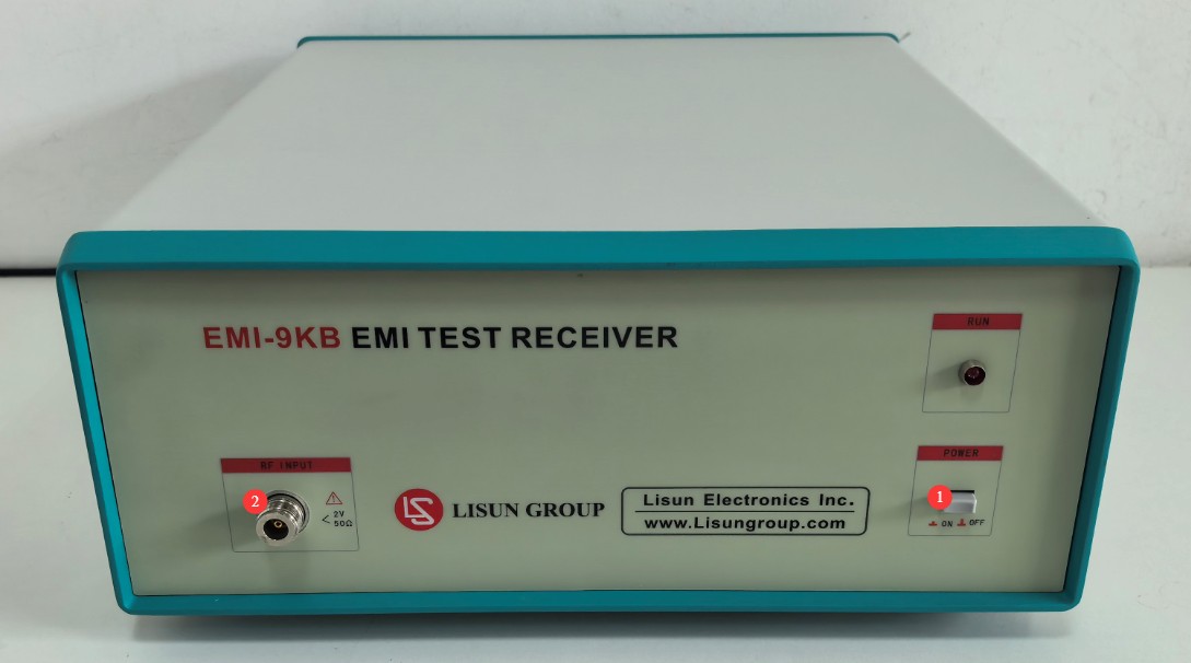
Figure 3-1
3.1.2 Rear Panel
See Figure 3-2.
| Number | Note |
| ① | Power cord jack, connected to Isolation Transformer |
| ② | Fuse |
| ③ | RS-232 communication port: Connect to a computer using an RS-232 communication cable. If the computer does not have an RS-232 port, you can use the standard RS-232-to-USB adapter cable to connect to the computer. Note: Do not use non-standard communication cables or adapters, as this may cause communication errors. |
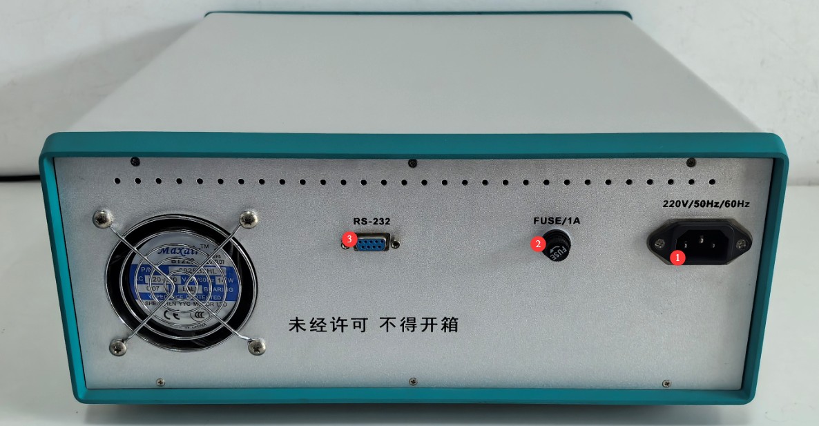
Figure 3-2
3.2 LISN-C Artificial Mains Network
3.2.1 Front Panel
See Figure 3-3.
| Number | Note |
| ① | RF output port; connect to the EMI-9KB using an N-to-BNC adapter and coaxial cable |
| ② | L/N switch, used to switch between the phase and neutral lines for testing interference signals |
| ③ | ARTIFICIAL HAND Interface, simulated hand connection terminal, used for testing handheld devices |
| ④ | 16A three-prong power cord connection port; can be connected directly to the EUT or via a 16A-to-10A adapter plug |
| ⑤ | 10A two-conductor power cord connection port, for direct connection to the EUT |
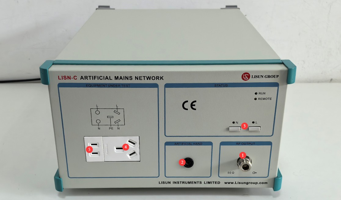
Figure 3-3
3.2.2 Rear Panel
See Figures 3–4.
| Number | Note |
| ① | Power cord with a 16A plug; it can be connected directly to Isolation Transformer or connected to Isolation Transformer via a 10A-to-16A adapter plug. |
| ② | Aviation-style connector, no connection required |
| ③ | 12V connector; connect one end to a 12V power adapter and the other end to Isolation Transformer |
| ④ | Grounding terminal: Connect using a copper grounding plate in accordance with the standard. |
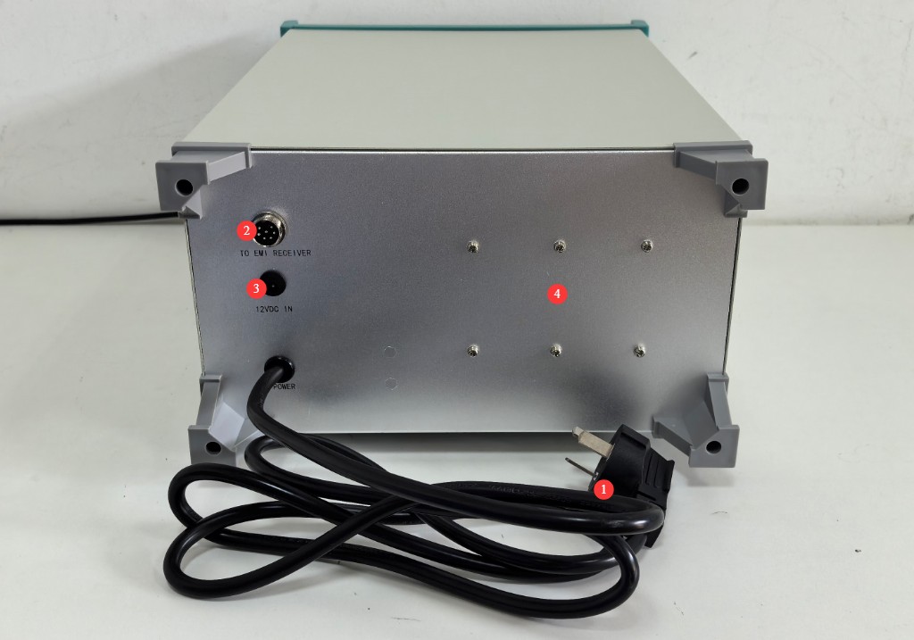
Figure 3-4
3.3 CDNE Coupling Decoupling Network
See Figures 3–5.
| Number | Note |
| ① | AE PORT, connected to Isolation Transformer |
| ② | EUT PORT, connected to the EUT |
| ③ | BNC-type RF output connector, connected to the EMI-9KB via coaxial cable |
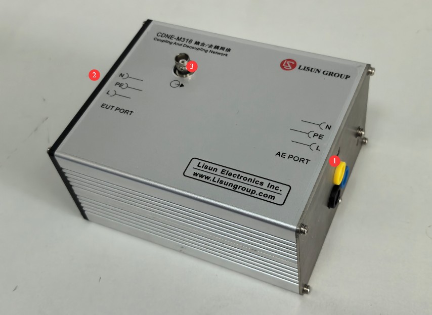
Figure 3-5
3.4 Isolation Transformer
3.4.1 Front Panel
See Figures 3–6.
| Number | Note |
| ① | Isolation Transformer 500VA Isolation Transformer is used to connect the EMI-9KB receiver, computers, printers, and other devices. |
| ② | Isolation Transformer is used to connect the LISN-C or CDNE and supply power to the EUT; it includes one 16 A receptacle. |
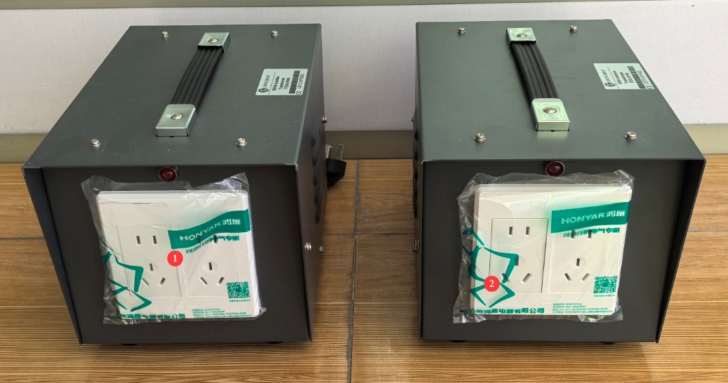
Figure 3-6
3.4.2 Rear Panel
See Figure 3-7.
| Number | Note |
| ①② | Simply connect the Isolation Transformer to the power grid using the power cord. The 500VA Isolation Transformer, which powers the EMI-9KB, should be connected to a 220V power grid; the 1kVA Isolation Transformer, which powers the EUT, must be connected to an appropriate power grid based on the EUT. |
| ③④ | Fuse |
| ⑤⑥ | Power Switch |
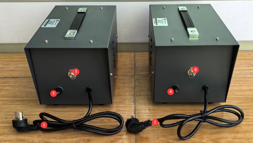
Figure 3-7
4. Software Installation and Overview
4.1 Software and Driver Installation
4.1.1 System Operation Requirements
Operating System: Windows 7 / Windows 8 / Windows 10 / Windows 11; Windows 10 is recommended;
Hardware Requirements: Pentium or higher processor, ≥2 GB of RAM, ≥1 GB of free hard disk space, and at least one available USB port;
Screen resolution: 1024×768 or higher is recommended.
4.1.2 Installation
See Figure 4-1.
| Number | Note |
| ① | EMI-9KB Receiver PC Software—Double-click to install |
| ② | RS-232-to-USB Adapter Driver: If you are using an RS-232-to-USB adapter, you must install this driver. |

Figure 4-1
4.1.3 Communication Port Settings
When you open the software for the first time, you may see a communication error message, as shown in Figure 4-2.
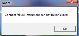
Figure 4-2
Click OK to open the software’s initial interface, then click Test > Port Settings, as shown in Figure 4-3.
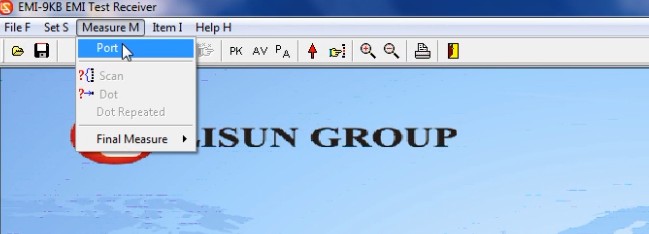
Figure 4-3
Simply select the correct communication port number manually, as shown in Figure 4-4.
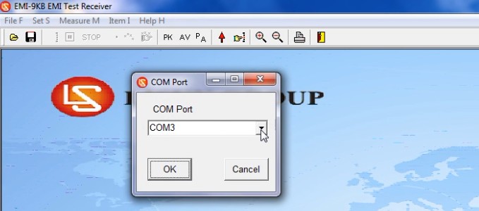
Figure 4-4
As shown in Figures 4 and 5, you can go to “My Computer” > “Properties” > “Device Manager” to confirm which communication port the device is using.
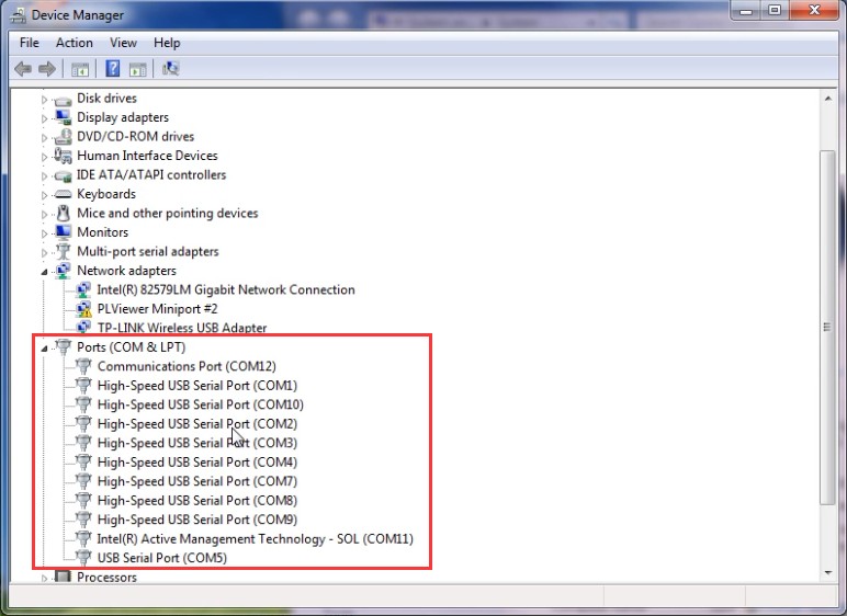
Figures 4–5
The next time you open the software, it will open directly to the initial interface. Note: If the communication port has changed, you will need to reselect the correct communication port.
4.2 Introduction to Software Interface Features
4.2.1 File Menu
4.2.1.1 Drop-down List
See Figures 4–6.
| Number | Note |
| ① | Open the EMC file |
| ② | Save the test results as an emc file. Note: emc files can only be opened using the LISUN EMI-9KB software. |
| ③ | Test Report Settings |
| ④ | Print a report that includes final test point data |
| ⑤ | Print a report that includes data on points of interest |
| ⑥ | Exit the software |
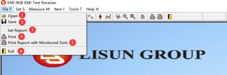
Figures 4–6
4.2.1.2 Report Option Information
When saving or printing a test report, the following screen appears first, as shown in Figure 4-7.
| Number | Note |
| ① | Save/Print Final Inspection Point/Focus Point Data? |
| ② | Fill in the test-related information |
| ③ | Fill in the Laboratory Information |
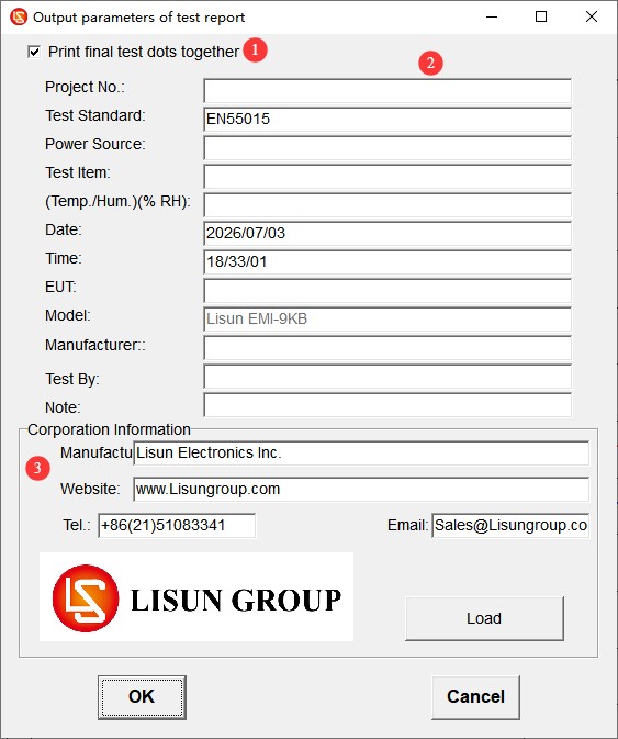
Fig. 4-7
4.2.2 Settings Menu
4.2.2.1 Drop-down List
See Figures 4–8.
| Number | Note |
| ① | Test Standards: Select, Add, Modify, or Delete Standards |
| ② | Test parameters: No changes are necessary; simply use the default settings. |
| ③ | System Calibration: Used by professional engineers when commissioning equipment; this feature is not required during normal operation of the equipment. |
| ④ | Attenuators: Select based on actual conditions |
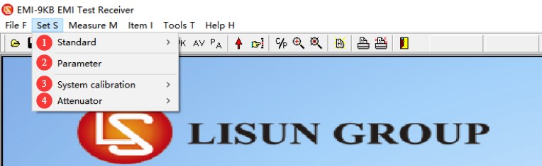
Figure 4-8
4.2.2.2 Test Standard Options
See Figures 4–9.
| Number | Note |
| ① | Selection Criteria: You can only select criteria that have been added previously; you cannot modify their parameters. |
| ② | Add, modify, or delete standards. Note: Please proceed with caution; all standards and limit curves are added according to the standards. If you have other standard data not included in our software, please send the relevant standards to us, and we will add them for you. |
| ③ | Absorbing Clamp, voltage probes, CDN network correction. Note: For use only by LISUN professional engineers when debugging software. |

Figure 4-9
4.2.2.3 Attenuator Options
See Figure 4-10.
| Number | Note |
| ① | Do not use an attenuator |
| ② | When using an attenuator, please select and enter the correct attenuation parameters in the software. |
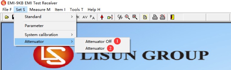
Figure 4-10
Note: Please configure the software correctly based on your actual usage; otherwise, the test results may be significantly skewed.
4.2.3 Test Menu
See Figure 4-11.
| Number | Note |
| ① | For communication port settings, see 4.1.3 |
| ② | Scan: Perform a scan test according to the criteria and parameter settings selected at that time. |
| ③ | Spot Test: If you only want to view data for a specific frequency point, click here to manually enter the frequency and run the test. |
| ④ | Final Test: After the scan test is complete, if you want to test the specific data for certain points again, you can perform a final test. |
| ⑤ | Automatic Final Test: The software automatically selects representative frequency points based on the test results for the final test. |
| ⑥ | Manual Final Test: Users manually add the frequency points they want to test based on their own needs. |
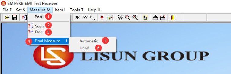
Figure 4-11
4.2.4 Display Menu
See Figure 4-12.
| Number | Note |
| ① | The graph shows both the default PK and AV lines. |
| ② | Add a monitoring point; this feature works the same as in the final test in version 4.2.3, and you can manually set the frequency points. |
| ③ | Display data that falls outside the limit curve |
| ④ | Display the data for the final test point |
| ⑤ | After performing two consecutive scan tests, you can click to compare the results of the two tests. |
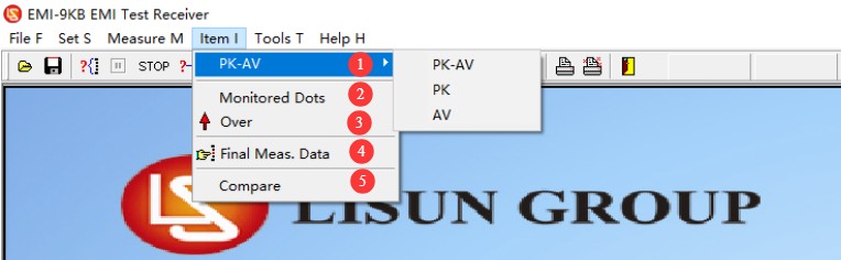
Figure 4-12
4.2.5 Introduction to Navigation Bar Shortcuts
See Figure 4-13.
| Number | Note |
| ① | Open the EMC file |
| ② | Save as an emc file |
| ③ | Scan Test |
| ④ | Pause Testing |
| ⑤ | Stop Testing |
| ⑥ | Spot Measurement |
| ⑦ | Automated Final Testing |
| ⑧ | Manual Final Testing |
| ⑨ | Display Curves: PK, AV, PK+AV |
| ⑩ | Display data that falls outside the limit curve |
| ⑪ | Display data for the final checkpoint |
| ⑫ | Show or hide data at overlapping points (hiding data at overlapping points makes the curve clearer) |
| ⑬ | Zoom In/Out: You can zoom in on the curve for easier viewing. After clicking, scroll the middle mouse button wheel in the curve display area to zoom in or out. |
| ⑭ | Test Report Settings |
| ⑮ | Print a report that includes final test point data |
| ⑯ | Print a report that includes data on points of interest |
| ⑰ | Exit the Software |
| ⑱ | Displays the parameters of the device’s internal modules; intended solely for use by professional engineers during debugging. |
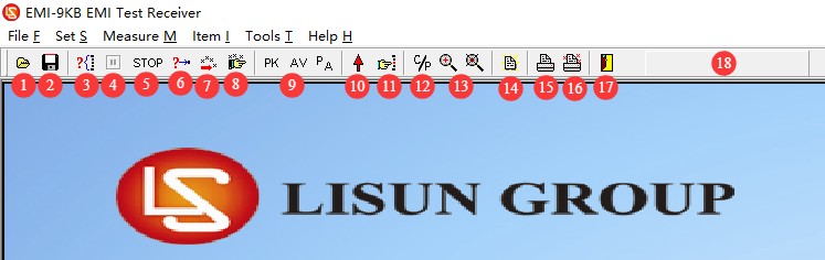
Figure 4-13
5. Preparations Before the Test
5.1 Requirements for Setting Up the Test Environment
Standard Procedure (Shielded Chamber): Formal compliance testing must be conducted in a code-compliant Electromagnetic Shielding Cabinet, which completely isolates the test subject from external environmental interference, ensuring the most accurate test results. The LISUN SDR series of Electromagnetic Shielding Cabinet may be used for this purpose.
Testing Plan (Standard Room): If a shielded room is not available, select a separate room with an area of at least 15 square meters that contains no other equipment generating strong electromagnetic interference; the ground floor is the optimal location, as it facilitates grounding and results in lower grounding resistance.
The test area must be at least 0.8 meters away from walls and other conductive objects to prevent electromagnetic wave reflections from affecting the test results.
5.2 Layout Diagram of the Standard Test Environment
5.2.1 Test Setup for Conducted Disturbance Testing of a Single Cable EUT
See Figure 5-1 (adapted from CISPR-16-2-1, Figure 11).
| Number | Note |
| ① | Metal wall, 2 m × 2 m |
| ② | EUT |
| ③ | An extra-long power cord that folds back and forth to measure 2 cm × 30 cm |
| ④ | LISN-C Artificial Mains Network (AMN) |
| ⑤ | Coaxial Cable |
| ⑥ | EMI-9KB Receiver |
| B | Refer to the grounding connection points and use a copper grounding plate to make the connection. |
| M | Connect the LISN-C and EMI-9KB using an N-BNC adapter and coaxial cable |
| P | Connect the EUT power cord to the LISN-C |
| The tolerances for cable length and distance should be as close as possible to those in actual applications. | |
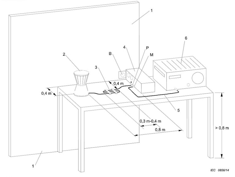
Figure 5-1
Depending on the specific circumstances, you may refer to other standard test layout diagrams. The following are the key points for the layout:
Benchtop equipment: Place on an insulated test bench 0.8 m high, with the rear of the unit 40 cm from a grounded metal plate and at least 80 cm from other conductive objects; fold any excess length of the power cord into an S-shaped bundle 30–40 cm long; do not twist the cord;
Floor-mounted equipment: Place the equipment on an insulating panel (12 mm thick) laid on the floor, with a grounded metal plate measuring at least 2 m × 2 m beneath the insulating panel; all sides of the equipment must be at least 50 cm from the edge of the metal plate and at least 80 cm from the LISN; fold any excess length of the power cord in the center;
Lighting Products: Lamps with built-in ballasts and separate ballasts shall be placed on insulated supports in accordance with the standards; the power cord shall be 0.8 m long and laid out straight; the equipment grounding terminal shall be connected to the reference ground;
Handheld equipment without grounding: In accordance with the standard, wrap metal foil around the grip area to simulate a hand; connect the other end of the simulated hand to the simulated hand interface on the LISN;
5.2.2 Test Setup for Radiated Disturbance Testing of EUTs with a Single Cable
See Figure 5-2 (adapted from CISPR-16-2-1, Figure 23).
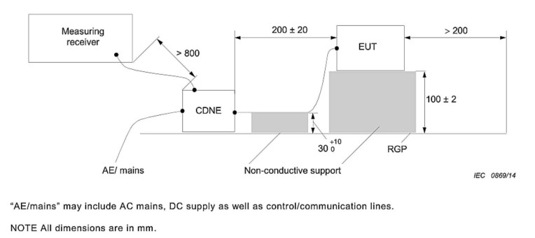
Figure 5-2
Note 1: The CDNE method applies only to lighting and similar electrical equipment; standards for household appliances, IT equipment, and power tools (CISPR 14/CISPR 22) do not permit the use of CDNE as a substitute for an anechoic chamber or open-field test.
Note 2: CDNE substitute radiation testing may only be used for preliminary R& D testing and may not be used for third-party compliance certification testing.
The following are the key points for the assignment:
Place an insulated wooden block 10 ± 0.2 cm high on the reference grounding metal plate, and gently place the device under test on top of the wooden block;
The equipment under test is connected to the CDNE’s EUT port via a power cable 20 ± 10 cm in length; the cable is supported by an insulating spacer 4 ± 0.2 cm high to keep it parallel to the metal plate;
The RGP (Reference Ground Plane) is a reference grounding metal plate on the ground; the CDNE unit is placed directly on the grounding metal plate to ensure good contact between the enclosure and the metal plate;
The CDNE’s AE port is connected to the power supply from Isolation Transformer output;
See Figure 5-1 for the location of the EMI-9KB and other test environments.
5.3 Wiring Diagram
See Figure 5-3.
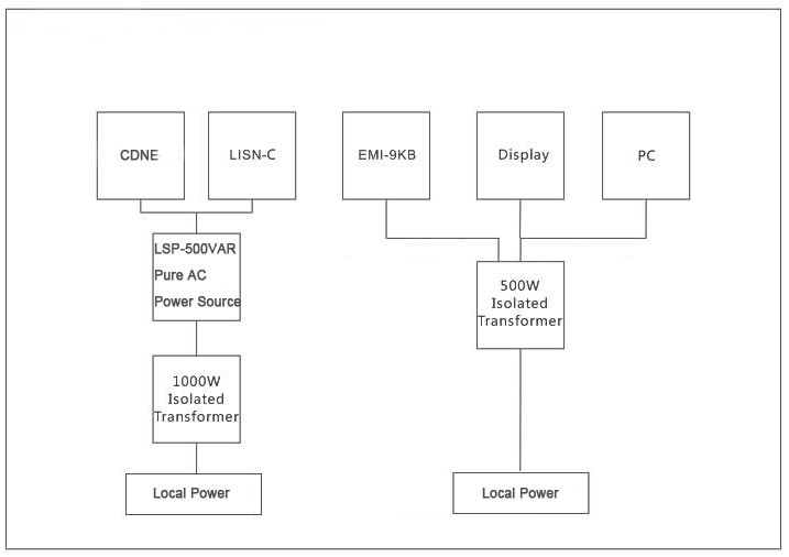
Figure 5-3
Note: The LSP series consists of LISUN pure sine wave regulated power supplies, which are used to provide a stable, pure sine wave AC power supply to the EUT. These are available for purchase as an optional accessory.
6. Conducted and Radiated Immunity Test Procedures
6.1 Preparations
Refer to Chapters 3 and 5 to set up the test environment and connect all system equipment and the EUT.
6.2 Warm-up Upon Startup
Refer to Section 2.2.1. Power on all equipment and the EUT in the correct sequence and manner, and ensure that the EUT is in normal operating condition. As required by the standard, the EUT must be allowed to warm up to a stable operating state (typically 15 to 30 minutes) before testing.
6.3 Confirmation of Test Parameters
6.3.1 Selection of Standards
Select the appropriate standard. For example, if you are using the LISN-C to test for conducted emissions, select EN 55015; if you are using the CDNE-M16 to test for radiated emissions, select EN 55015 CDNE-M3.
6.3.2 Attenuator Settings
Refer to Section 4.2.2.3 to verify that the software attenuator settings are correct based on whether an external attenuator is used and its parameters. If a 20 dB attenuator is used, refer to Figure 6-1 for the settings.
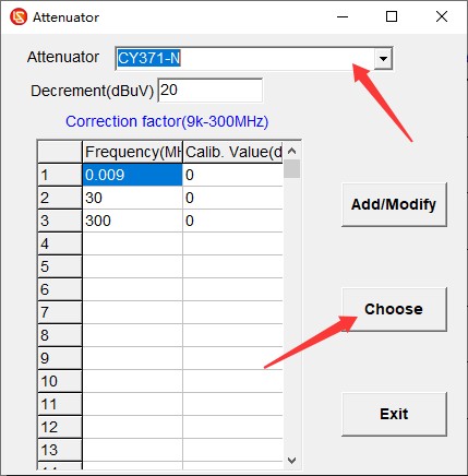
Figure 6-1
6.4 Scan Test
6.4.1 L/N Phase Switching in the LISN-C
Both the L phase and the N phase must undergo conducted immunity testing. After testing one phase, you must switch the L/N phase switch on the LISN-C to test the other phase. Note: Do not switch the L/N phase switch during the test.
6.4.2 The ARTIFICIAL HAND Interface of the LISN-C
When testing Class I and Class II ungrounded handheld power tools (handheld drills, angle grinders, electric saws, polishers, etc.), ungrounded handheld small household appliances (handheld hair dryers, handheld vacuum cleaners, handheld food processors, etc.), and handheld medical electrical equipment (dental handpieces, handheld physical therapy devices, in accordance with IEC 60601-1-2), this must be used.
Copper wire and 0.05 mm-thick copper foil must be used to connect the LISN-CARTIFICIAL HAND interface to the EUT handle and housing in order to establish human body simulation coupling.
6.4.3 General Scan Test
Click “Scan Test,” wait for the scan to complete. If an error occurs, click “Stop Test,” make the necessary adjustments, and then restart the test. Once the scan is complete, see Figure 6-2.
Red line: Quasi-Peak (QP) limit line;
Blue line: Average (AV) limit line;
Green curve: Peak (PK) test curve;
Blue curve: Average (AV) test curve.
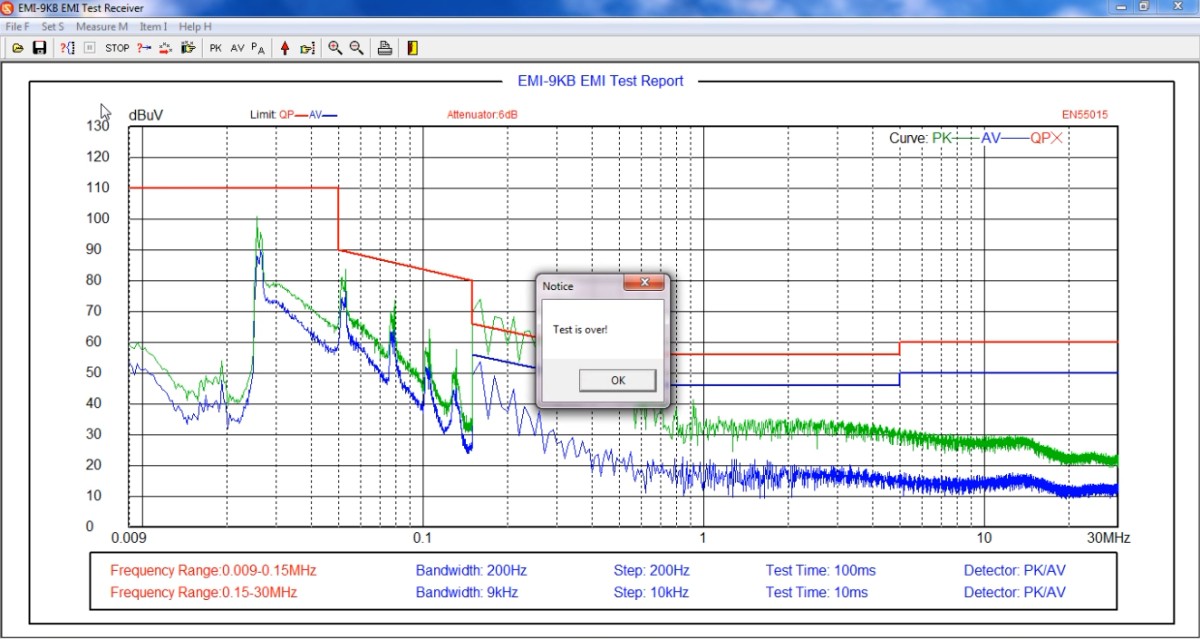
Figure 6-2
6.5 Final Exam
If the average values (AV) of the test results are all below the limit curve, and the peak values (PK) are all below the quasi-peak (QP) limit curve, then the EUT meets the standard requirements, because the actual quasi-peak (QP) value measured during testing will not exceed the peak (PK) value. If the tested peak value (PK) exceeds the quasi-peak (QP) limit curve, the EUT is not necessarily non-compliant with the standard; a final test must be conducted.
6.5.1 Automatic Final Testing
Enter the number of frequency points to be tested, and the software will automatically select frequency points based on the test curve to perform the final test, as shown in Figure 6-3.
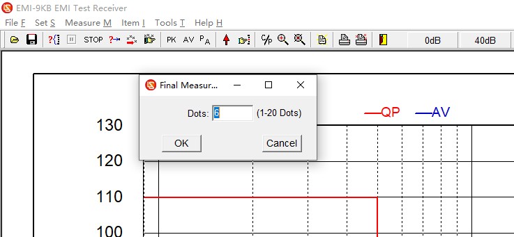
Figure 6-3
6.5.2 Manual Final Testing
In the software test curve area, right-click on the point where the final test is to be performed, as shown in Figure 6-4.
| Number | Note |
| ① | Add Endpoint |
| ② | Delete the Endpoint |
| ③ | After adding all the required final test points, click “Start Final Test.” |
| ④ | If you no longer wish to participate in the final test, click “Cancel Final Test.” |
| ⑤ | The blue diamonds indicate the locations of the added final test points |
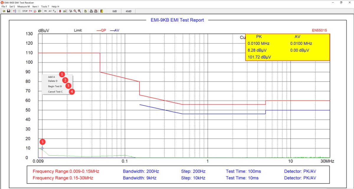
Figure 6-4
6.5.3 Adding Points of Interest
See Figure 6-5.
| Number | Note |
| ① | Click to clear all frequency points and data from the current screen |
| ② | Tap to edit the frequency point status; tap again to exit the frequency point editing mode. |
| ③ | Frequency points to be edited; you can manually enter each frequency point |
| ④ | You can directly load the frequency point file you edited earlier. |
| ⑤ | You can save the frequency point data file you are currently editing so that it can be directly accessed during the final test. |
| ⑥ | Click “Create Data” to directly read the test data for the corresponding frequency points from the current test report. |
| ⑦ | Read the test data for the corresponding frequency points from the current test report |
| ⑧ | Click “Clear Data” to clear the retrieved data. |
| ⑨ | Click OK to save the current screen’s focus point data to the test report. |
| ⑩ | Click EXIT to exit immediately without saving the focus data on the current screen. |
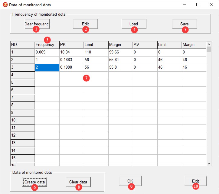
Figure 6-5
6.5.4 Interpretation of Final Test Data
See Figure 6-6. The red X marks the quasi-peak (QP) values from the final test. If all quasi-peak (QP) values from the final test are below the quasi-peak (QP) limit curve, the EUT meets the standard requirements. Otherwise, it does not meet the standard requirements.
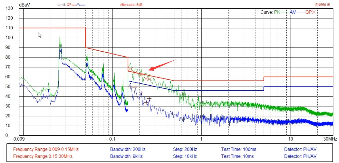
Figure 6-6
6.6 Save and Print the Test Report
See Section 4.2.1 to save or print the test report.
6.7 Procedure for Shutting Down the System at the End of a Test
Ensure the equipment is in the “Test Stop” state → Disconnect the coaxial cable on the LISN/CDNE side → Turn off the EUT power → Turn off the receiver and computer → Turn off Isolation Transformer.
7. Daily Maintenance and Care of Equipment
7.1 Routine Use and Maintenance
7.1.1 Maintenance of the Exterior and Interfaces
After each use, wipe the surface of the equipment with a dry, soft cloth to remove dust; do not use highly corrosive organic solvents such as gasoline, acetone, or thinners; to clean stubborn stains, use a lint-free cloth dipped in a small amount of anhydrous ethanol to wipe the area quickly, and dry it immediately afterward.
Inspect the BNC connectors, power connectors, and terminal blocks monthly; remove any oxidation to ensure good contact. When the connectors are not in use, cover them with protective caps to prevent dust from entering.
Each piece of equipment is assigned to a specific user; unauthorized personnel are prohibited from operating it. Do not remove the equipment casing without the manufacturer’s authorization; any hardware damage resulting from unauthorized disassembly is not covered under the free warranty.
7.1.2 Maintenance of Cables and Accessories
Avoid bending coaxial cables sharply, stepping on them, or subjecting them to pressure from heavy objects. When storing them, coil them loosely to prevent the internal conductors from breaking.
Handle precision accessories such as attenuators and connectors with care to prevent internal damage caused by dropping them.
Software settings must not be modified arbitrarily, and the built-in standards and calibration data must not be altered without authorization.
7.2 Storage Specifications
7.2.1 Storage Environment Requirements
Temperature: 5°C to 35°C; relative humidity: ≤65% RH; dry, dust-free environment free of corrosive gases.
7.2.2 Long-Term Storage Operations
Turn off the power and unplug all cables; clean the equipment and wrap it in dust-proof film; turn on the power for 30 minutes each month to prevent moisture damage to the components.
7.3 Calibration Interval Requirements
To ensure the measurement accuracy and operational reliability of the equipment, it is recommended that it be sent periodically to a qualified third-party metrology laboratory for calibration. The recommended calibration interval is 12 months. Users may determine the specific calibration interval based on frequency of use, environmental conditions, and quality system requirements.
8. Troubleshooting and Resolving Common Problems
| Fault Symptoms | Procedure |
| Various error messages may appear while using the software, such as the software failing to open or errors occurring during scanning. | Make sure you’re logged in to your computer with an administrator account, and make sure the software is running with administrator privileges. |
| The software worked fine during the scan test, but froze during the final test. | The final test has stricter communication requirements than the scan test. Please ensure that you are using only our original communication cable and no other cables or extension cords; please ensure that you are using the communication port on the back of the desktop computer (USB ports on laptops and those on the front of desktop computers often do not provide sufficient power, which can affect communication); if that still does not work, please try adding an RS232 port to your computer and use only an RS232 cable for communication—do not use an RS232-to-USB adapter. |
| LISN-C has no RF signal output | Check the 12V power adapter connection, ensure the RF output BNC connector is not loose, and verify that the N-to-BNC adapter is in good condition. |
| Test results are generally lower or higher than expected | Please verify that the software attenuator settings match the actual conditions. |
| Test results are always close to background noise, and the EMI receiver cannot detect any signals. | Check the coaxial cable connection; replace the coaxial cable and try again. |
| Excessively high background noise and significant fluctuations in test data | Verify that all equipment in the system uses Isolation Transformer; optimize the grounding system to reduce ground resistance; turn off other electrical equipment in the laboratory or conduct testing inside a shielded room. |