
 English
 中文简体
中文简体 English
 Русский
 Español
 Português
 Türkçe
 العربية
 Deutsch
 Polski
 Italiano
 Français
 한국어
한국어 ไทย
ไทย Tiếng Việt
 日本語
日本語





























Rohs 2.0 Test Equipment
User's Manual
Applicable LISUN models: EDX-4
After years of research and development, LISUN officially launches the new RoHS 2.0
Pyrolysis Phthalates Detector – EDX-4. Developed and manufactured in accordance with the standard “Q31/0110000048C001-2015 GC-9860 Series Gas Chromatograph.”
The working principle of the EDX-4:
GC is a technique for the separation and analysis of multicomponent mixtures. It primarily utilizes differences in boiling points, polarity, and adsorption coefficients of the components in the sample to separate them within the chromatographic column, and then performs qualitative and quantitative analysis on the separated components. A gas chromatograph uses gas as the mobile phase (carrier gas). When the sample is introduced into the injector and vaporized, it is carried into the packed column or capillary column by the carrier gas. Due to differences in the boiling points, polarity, and adsorption coefficients of the components in the sample, they are separated within the column. Then, a detector connected to the rear end of the column detects each component sequentially based on their physical and chemical properties. Finally, the gas chromatogram for each component is sent to the chromatography workstation via a local area network (or the Internet), where the workstation records and analyzes the chromatograms to generate analytical reports for each component.
This analytical method is characterized by high separation efficiency, fast analysis speed, and minimal sample consumption. Therefore, it has been widely applied in fields such as petrochemicals, biochemistry, medical health, health quarantine, environmental protection, the food industry, and clinical medicine. GC has addressed issues related to quality inspection of intermediates and industrial products, scientific research, pollution detection, and production control in these areas.
The EDX-4 gas chromatograph incorporates the latest high-integration industrial-grade chips, bus technology, Ethernet technology, micro-flow gas control technology, and data processing technology. It features optimized temperature control programs and gas flow control, fundamentally enhancing the instrument’s reliability and maintainability.
EDX-4 Pyrolysis Phthalates Detector
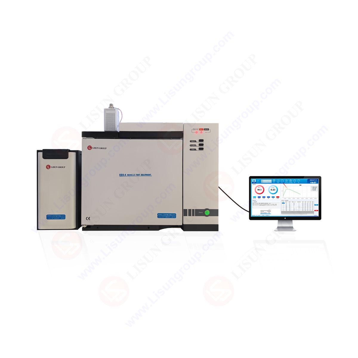
About

EDX-4 Pyrolytic Phthalates Detector: Main Functions and Features:
Equipped with a technologically advanced 10/100M auto-adaptive Ethernet communication interface and an integrated IP protocol stack, the EDX-4 gas chromatograph enables effortless long-distance data transmission via corporate intranets or the Internet. This feature streamlines the setup of laboratories, simplifies the configuration of lab settings, and enhances the management of analytical data.

Equipped with three separate connection processes, which can be linked to local processing (laboratory site), department supervisors (production plant managers, etc.), and higher authorities (Environmental Protection Agency, etc.) . This feature enables both department supervisors and higher authorities to monitor the instrument’s operation and analyze data results in real time.

Equipped with the NetChrom™ workstation, which is capable of supporting multiple chromatographs simultaneously. It facilitates data processing and remote control, simplifies document management, and minimizes users’ laboratory investment and operational expenses to the greatest extent possible.

Connects via the Internet, enabling remote diagnostics and software updates with the user’s permission.;
Equipped with two operating systems in both Chinese and English that can be easily switched between;

Users can assign custom names to the temperature control zones;

It utilizes a multi-processor parallel processing method, enhancing stability and reliability. It offers a range of high-performance detectors, including FID, TCD, ECD, FPD, and NPD. The ability to install up to three detectors simultaneously facilitates the analysis of complex samples. It also provides the flexibility to conveniently purchase and install additional detectors after the initial purchase.
Modular structural design facilitates convenient maintenance and easy updates or iterations in the future.;

The sampling time is 20 minutes, with direct solid/liquid sampling for ultra-fast results;

No chemical pretreatment is required; direct solid/liquid sampling is possible;

Featuring a world-leading ceramic heating module with less than 10% degradation over

60000 hours;
Features a programmable temperature ramp function in 5-degree increments per stage;

Low operating costs as low as 8000 yuan per year;

Capable of remotely controlling the instrument, displaying all operations, and saving operation logs;

No chemical reagents are involved, no environmental assessment is required, and no laboratory construction is needed.

Contents

Maintenance of Key Components
Injector and Replacement of Septa, Liners, O-Rings, and Graphite Ferrules – – – 09, 10 Flame Ionization Detector (FID) Maintenance, Nozzle Replacement – – – – – – – 10, 11 Thermal Desorption Instrument and Replacement of Syringe Needles, Septa, Liners, and
O-rings – – – – – – – – – – – – – – – – – – – – – – – – – – – – – – – – – – – – – – – 12, 13, 14
Installation and Replacement of the Chromatography Column – – – – – – – – – – – 15, 16
Instrument Installation
Installation Environment Requirements – – – – – – – – – – – – – – – – – – – – – – – – – – – 17, 18, 19
A. The RoHS Phthalates Testing Procedure
Testing Operation Procedure
Liquid Sample Preparation – – – – – – – – – – – – – – – – – – – – – – – – – – – – – – – 29, 30
Instrument Testing Procedure
C. Standard Solution Data Processing
Construct Component Table and Calibration Curve; Standard Solution Integration
and Create New Component Table – – – – – – – – – – – – – – – – – – – – – – – – – – – 36, 37
D. How to Generate Sample Test Results
Open the Processed Standard Liquid Chromatogram, Overlay Chromatograms, and
Safety Precautions EDX-4 Appearance


Front View of the Gas Chromatograph: Please strictly follow the warning signs below to avoid injury to users and prevent damage to the equipment.

Warning: Heating Element (Injector) This sign indicates danger. Be careful! Stay alert!



Guangzhou Jingu Scientific Instruments


1. Improper operation may result in serious personal injury.
Remote Rate Final Temp EDX-4 Thermal Cracking Ortho-Xylene Detector 2. Failure to use the device in accordance with the User Manual may result in personal injury or equipment damage. Precautions




A. High-Temperature Hazard:
StartPrepRunStopWhen the instrument is in operation, keep it away from heat-generating components. Before performing maintenance or disassembly, be sure to turn off the power first and wait until the instrument has completely stopped operating and the high-temperature parts have cooled down completely!




●The sampler, detector, column compartment, and rear exhaust port will still be at a relatively high temperature while the instrument is operating or shortly after it is turned off. Avoid
Do not touch these parts to avoid burns. Before replacing any parts, please wait until they have cooled down or take protective measures!
●Be aware of the hot gases emitted as the instrument cools down to prevent burns!
●Do not place flammable items behind the instrument to prevent ignition.
Power Guangzhou Jingu Scientific Instruments EDX-4 Pyrolysis Phthalate Detector Warning/WARNING: Electrical Hazard! Non-professionals are prohibited from operating this equipment. ELECTRIC SHOCK—AUTHORIZED PERSON ONLY. Pyrolyzer Power On Button ● The polyethylene gas supply lines should be kept away from the rear exhaust port to prevent the hot gases from melting the gas supply lines, which could cause greater danger!


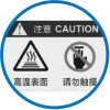


Warning / WARNING |
Warning / WARNING |
| Hot Surface Do Not Touch | Hot Surface Do Not Touch |
Back View B. High Voltage Hazard:

●Do not touch plugs with wet hands to prevent electric shock, electrical leakage, or fire.
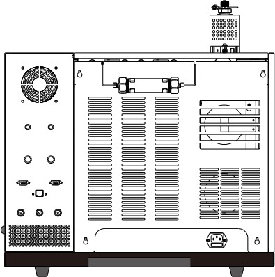
Cold Trap Gas Fitting Gas Valve Cooling Fan Do not plug in or unplug the device while it is powered on to avoid damaging the equipment!
●Do not remove the instrument cover while the instrument is running. The high voltage inside could cause personal injury.




●When replacing fuses or performing maintenance, please unplug the power cord first. Turning off the power switch does not completely cut off the high voltage.
WARNING: Non-professionals must not open this unit! NON-PROFESSIONALS DO NOT OPEN Cleaning Port Cleaning Valve C. Gas Source Hazards: ● If the power cord is worn out or damaged, it must be replaced immediately.




| DANGER | DANGER | |
 |
 |
Do Not Plug In or Unplug While Powered On. HOT PLUGGING IS PROHIBITED |
Cleaning Port
Carrier Gas Outlet Flow Stabilizer Valve Triggered Remote●It is necessary to follow the relevant regulations for the transportation, storage, management, and safe use of gas cylinders!
Injection Port LAN Pressure Regulator Carrier Gas Makeup Hydrogen H2 Air Carrier Gas Inlet ●When using hydrogen as a carrier gas or FID fuel gas, be aware that hydrogen may flow into the column box and pose an explosion hazard. Therefore, before connecting the pipeline,
Gas Chromatograph TP PRO Model Number: SN Serial Number: Measurement Object: Routine Chromatographic Analysis Components Always close the gas source. After installing the chromatographic column and connecting the sample and detector connectors, check all connections, tubing, and valves before opening the hydrogen gas source.





●When analyzing special samples (toxic), the exhaust should be vented to a safe outdoor location


to prevent indoor pollution or poisoning. Note: Air source inlet, Electrical/Pneumatic Port, Electrical Socket, Ports, Power Outlet & Switch


0201
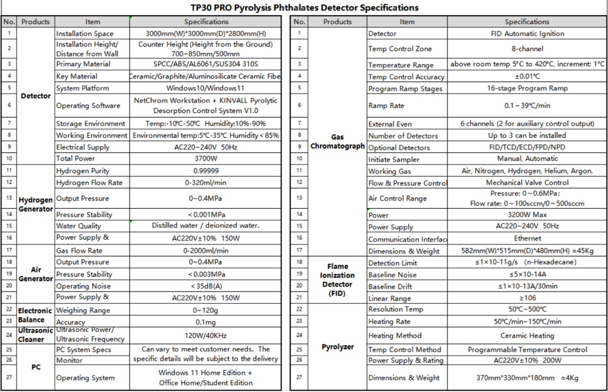
Technical Specifications

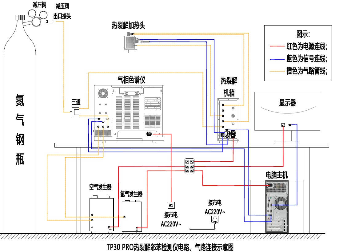
Schematic Diagram of Electrical and Pneumatic Connections

MonitorMonitorComputerComputerPressure-reducing valvePressure-reducing valveOrange gas cableOrange gas cableBlue signal cableBlue signal cableRed power cableRed power cablePyrolyzerPyrolyzerHydrogen generatorHydrogen generatorAir generatorAir generatorHeating elementHeating elementGas chromatographGas chromatographNNitrogen CylinderNitrogen Cylinder


Packing List

| EDX-4 Pyrolysis Phthalates Detector Packing List | EDX-4 Pyrolysis Phthalates Detector Packing List | EDX-4 Pyrolysis Phthalates Detector Packing List | EDX-4 Pyrolysis Phthalates Detector Packing List | EDX-4 Pyrolysis Phthalates Detector Packing List |
| Item | Products | Main Specifications and Model | QTY | Remarks |
| 1 | Gas Chromatograph | Equipped with an FID, a capillary sampler system, a split/custom-designed injection port, and a cold trap | 1 SET | FID + Mechanical Valve Control |
| 2 | Gas Chromatograph Accessories Kit | User Manual (or electronic version if not included) Certificate of Conformity / Factory Inspection Report (1 copy) Accessories List / High-Temperature-Resistant O-Ring (? 5.0*1.9, 1 pc) Gas Line Hose (⌀ 3 – 30 meters, white)/ Chromatographic Quartz Liner (⌀ 6.3×78.5, 1 pc)/ Ignition Torch (1 pc) Three-Way Connector 3 mm (2 pcs)/ Leak Detection Fluid (1 can) Crescent Wrenches (3 different sizes x 1)/Phillips Screwdriver (? 5, 1 pc) Gas Line Nuts (M8*1 ? 3.2, 20 pcs)/Column Nuts (M5 × ? 1.0, 4 pcs)/Sampling Syringes (10 μl / 1 μl, 1 pc each) Three-Way Connectors (M8 × 1 × 3.2, 2 pcs) / Soap Film Flowmeter (1 pc) Pressure Regulator Outlet Connectors (M8×1, 3 pcs)/ Ethernet Cable (2 meters, 1 pc)/ Graphite Gaskets (⌀ 0.5, 10 pieces; ⌀ 3, 10 pcs)/ Chromatographic Quartz Liner (1 pc)/ Plugs (⌀ 3, 5 pcs)/ Injection Septa | 1 SET | Packed with a Gas Chromatograph |
| 3 | Workstation | NetChrom Chromatography Workstation Software | 1 SET | |
| 4 | Capillary Column | Phthalate-Specific Chromatographic Column | 1 SET | |
| 5 | KINVALL EDX-4 Pyrolyzer | Features both thermal desorption and pyrolysis functions. Programmable temperature control. Desorption temperature: 50°C to 500°C. Heating rate: 50°C/min to 150°C/min. | 1 SET | Heating Element and Enclosure |
| 6 | KINVALL Thermal Desorption Control System | V1.0 | 1 SET | |
| 7 | Hydrogen Generator | Flow Rate: 0–320 ml/min, 0.4 MPa | 1 SET | |
| 8 | Air Generator | Flow Rate: 0–2000 mL/min, 0.4 MPa | 1 SET | |
| 9 | Electronic Scale | Accuracy: 0.1 mg Weighing Range: 0–120 g | 1 SET | |
| 10 | Nitrogen Cylinder | 99.999% High-Purity Nitrogen, equipped with a pressure-reducing valve | 1 SET | user-provided |
| 11 | PC | Brand-Name Commercial Desktop PC + Monitor + Genuine Operating System | 1 SET | Windows 10/Windows 11 |
| 12 | Standard Solution | Four phthalate reference standards and others | 1 SET | |
| 13 | Standard Refrigerator | Storage of Reference Materials | 1 SET | user-provided |
| 14 | Tool Kit | Weighing Paper 500 pieces / Tweezers 1 pair / Sample Cutting Knife 1 piece / Hexane 500 ml, Nitrile Gloves 1 box / 1000-ml Beaker 1, 1.5-ml Solvent Bottles 10 / 200-ml Beaker 1, Syringe Needles 4 / Quartz Cotton 1 g, Dongle 1 / Graphite Gasket 10 pcs Septa 10 pcs / Solvent Bottles 10 ml 1 pc | 1SET | |
| 15 | Consumables Kit | Sampler Quartz Tubes (100 pcs), Sampler Quartz Outer Tube (1 pc), Sealing Film (1 bag) | 1SET |
07
Test Procedure

| 1. Open below |
Nitrogen cylinder, Air generator, Hydrogen generator   |
| 2. Power on below |
Computerized Pyrolyzer Chromatograph   |
yh d
| 3. Launch the software |
Connected. Successfully activated “Channel 1.” Execute the “Ph tha late” method   . . |
| 4. Start the thermal desorption control system |
Load the test heating program |
| 5. Waiting |
Wait until the Chem Lab software displays “Ready.” |
| 6. Cleaning |
Inject 5 µL of n-hexane and click “Start” on the thermal desorption control system . . |
Detection Process Diagram
5 f plsContinuous testing on sets of sam e

p h l PASS & out ut t e resu ts

onten 700 ppm

content <700 ppmCt

/
10. Formal Sample Analysis: Sample Test |
| 9. Cleaning Again |
Inject 5 µL of n-hexane |
| 8. Software Operation |
 |
| 7. Testing Standards |
Take 1 µL of the standards for testing |
| 11. Test Complete |
Inject 5 µL of n-hexane and run the cleaning procedure |
| 12. Chromatograph Software Operation |
Send the “Shutdown” method |
| 13. Waiting for it to cool |
Wait until “Equipment Parameter Status”: Oven temperature < 50°C; all other temperatures < 100°C |
| 14. Power Off Below |
Software Chromatograph Pyrolyzer   |
| 15. Turn off the following |
Nitrogen Cylinder, Air Generator, Hydrogen Generator   |
08
Maintenance of Major Components

1. Sample Injector
The main function is to introduce the sample into the GC column in a reproducible and
in a consistent manner. The sample introduced should be representative (unless otherwise specified), and no chemical reactions should occur during the introduction process.
Injector Structure
The injector is typically installed on the upper left front side of the column compartment, with its temperature and gas pathways set and controlled by the microcomputer.
controller. The structural composition is shown below.
Sample Inlet
Spacer Purge Carrier Gas
Sample Cap

Sample Injection Spacer
Traffic Diversion

Traffic Diversion
Sample tube
Housing
Liner

Detector-to-Detector
Column Nut
Chromatography Column
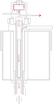
Structure Schematic Diagram (Left) Structure Schematic Diagram (Right) The injector’s gas path
The gas path consists of a carrier gas entering the chamber and flowing upward to sweep the
injection septum and then returns to be expelled through the septum purge channel; it is then divided into two paths through the sample tube: one path continues downward into the chromatographic column, and the other is blown toward the outside of the liner and expelled through the split channel. As shown in the diagram on the right above.
Replacement of the Sample Injector Pad

Long-term and frequent use can cause wear and leaks, leading to a drop in column pressure or instability, poor peak area repeatability, retention time drift, and increased baseline noise. High-quality injection needles can effectively extend the service life of the injector pad. Needles with a smooth surface, sharp tip, and no burrs are recommended (please consult LISUN’s after-sales service for purchasing).
Replacement Steps:

Turn off the gas chromatograph and make sure the column compartment and the injector are at room temperature. Unscrew the injector cap and use tweezers to remove the pad.
09
Maintenance of the Sample Injector

Be careful not to scratch the other components. Use tweezers to insert the new pad and gently press it down. Tighten the injector cap (over-tightening can cause damage or cause debris from the pad to fall into the injector).
Replacement of the Liner and O-Rings

Dirty samples can contaminate the liner, leading to abnormal baseline noise, ghost peaks, and other issues. The O-rings will lose their sealing function under high temperatures &
pressure. Generally, O-rings should be replaced each time the liner is replaced (O-rings are consumables, and liners can be reused after ultrasonic cleaning).
The replacement steps are as follows:
Turn off the gas chromatograph and make sure the samples are at room temperature. Unscrew
the largest nut on top, and slowly lift the entire nut assembly upward (be careful not to lift it too high or move it too far to avoid bending the connected gas lines). Use tweezers to
Hold the top end of the liner along with the O-ring and pull them out vertically. Take a new, clean liner, place a new O-ring on the top of the liner, and insert them.
Gently press it into the injector, then tighten the nut.
Installation of the Chromatographic Column

See the following section, “Installation and Replacement of the Chromatographic Column.”
Maintenance of F ID

2. Hydrogen Flame Ionization Detector (FID)
FID is a mass-sensitive detector known for its high sensitivity and wide linear range. It is relatively insensitive to changes in operating conditions, offering good stability. It is suitable for routine
analysis of major or trace components due to its fast response. When combined with capillary column technology, it can perform rapid analysis of trace amounts. It is one of the most widely
Used detectors in GC instruments.
The principle of FID: The sample to be analyzed is burned in a hydrogen flame, generating an ion current. Under the influence of a polarizing electric field, positive and negative ions move
directionally toward the collection electrode, thereby generating a weak electrical current signal. This signal is then amplified and processed by a microcurrent amplifier before being sent to the
chromatographic data processing system.
The combustion gas used by the FID is hydrogen. Do not open the hydrogen valve when the FID is disconnected from the column, as hydrogen may enter the column housing and cause an explosion.
When shutting down the instrument, close the hydrogen valve first, then the carrier gas valve after the instrument has cooled down.
The high-sensitivity FID requires the use of high-purity carrier gas, hydrogen, and air.
To prevent contamination of the detector, do not connect the column to the detector during column aging. The bottom of the detector can be sealed with a nut.
Before turning on the power, check that the electrical connections are correct, the gas connections are complete, and the types of gases meet the requirements.
When the detector is operating, the polarization voltage is 220–250 V.
Even when the instrument is turned off, there may still be high voltage on the polarization electrodes! Please take precautions to prevent electric shock!
Discharge to ground before operating!
10
Gas Chromatograph-FID

The Structure of a Hydrogen Flame Ionization Detector (FID)

The FI D is located at the top front of the GC. Its base is mounted on a heat conductor, which also houses the electric heating elements and temperature sensors. These
The components are connected to the temperature control system to regulate the heating.
temperature. The polarizing electrode is connected to the FID’s microcurrent amplifier’s
polarizing voltage output. The signal output from the collecting electrode is connected to the FID’s microcurrent amplifier via a low-noise cable. Hydrogen and air are introduced via stainless steel tubes from the connectors of the gas line control system located above the GC.
ignition wire
i online
collection bucket
wedding l
support plate
gasket
main body, negative high-voltage line
support
temperature sensor

heat conductor. . Electronic component

lower nut

stud nut
The Structure of the F-ID Diagram
Maintenance of F ID

The nozzle in the detector needs to be cleaned or replaced regularly.
Even during normal operation, deposits can form inside the nozzle (usually white silicon dioxide and black carbon-containing black carbon from column bleeding). These deposits can reduce sensitivity and cause chromatographic baseline noise and peak signals. Although it is possible to clean the
nozzle; simply replacing it with a new one is often more practical and faster. If you do decide to clean the nozzle, please be careful not to damage it.
11
Gas Chromatograph-FID

When analyzing different samples or changing the chromatography column, you need to replace the nozzle. For example, the nozzle used for packed columns is different from the one used for
capillary columns. You must install the appropriate nozzle before changing the column.
Steps to replace the nozzle:
Turn off the GC and make sure the column oven and detector are at room temperature. Remove the
Remove the chromatography column from the column oven. Open the top cover of the GC and remove the two screws holding the collector electrode support. Slide the collector electrode support out to
Separate it from the collector electrode assembly. Carefully lift the collector electrode
Remove the component carefully (be careful not to pull or tug on its connecting wires) and set it
Set it aside. Insert a socket wrench into the detector body and attach it to the nozzle, then unscrew it.
Turn the nozzle counterclockwise. Use tweezers to remove the detached nozzle and nozzle gasket, and manually unscrew the nozzle tube at the bottom of the nozzle. Obtain a new or thoroughly cleaned nozzle and reinstall it.
(Note that the nozzle gasket is a sealing component and must be replaced to ensure gas tightness).
PY-Heating Element

The PY Thermal Desorber is a sample pretreatment device that can seamlessly and efficiently
Interfaces with GC or GC-MS. It features an independent temperature control system and allows for direct solid/liquid sampling. Pre-desorption or thermal desorption can reduce sample
contamination of the GC or GCMS.
PY consists of two main parts: the chassis and the heating element. The chassis houses the electrical and temperature control components, while the heating element is the main body for the sample.

The system features a sampling needle that fits directly into the GC or GCMS injection port, facilitating both introduction and desorption. This setup ensures a seamless and efficient connection, optimizing the analytical process and maintaining the integrity of the system.
injection port, injection gas inlet, injection nut, cleaning outlet, protective tube, ceramic heating element, line tube, temperature sensor, sample tube, carrier gas inlets, support connect wire, connect to GC

The Structure of the Heating Element
12
PY-Heating Element PY-Heating Element


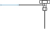
Pneumatic circuit of the heating element Replace the liner, O-ring, and injection septum


—Clean the outlet injection port. Turn off the PY, remove the heating element from the GC, and wait until all parts of the heating element have cooled to room temperature.



injection nut, gasket, upper nut assembly, O-ring. After removing the case, place the heating element flat on the desk, manually unscrew the injection nut to expose the sample septum, and use tweezers to lift and discard the




septum; Unscrew the upper nut assembly and gently move it aside



sample tube carrier gas liner tube (be careful not to pull off the two gas lines connected to the upper nut assembly). You will see the upper O-ring seated 3–4 mm from the upper port of the liner. Use tweezers to remove it; Remove the bottom support and bottom cover assembly, then unscrew the lower nut assembly and gently move it aside (be careful not to disconnect the single gas line connected to the lower nut assembly). You will then see the lower O-ring seated 3–4 mm from the lower port of the liner. Use tweezers to remove the line and the lower O-ring.




together.
Connect to GC case


main body: Diagram of the Pneumatic Circuit for the Heating Element
Replace the injection needle
1. Turn off the gas chromatograph, wait until all parts have cooled to room temperature, then disconnect the heating element and all gas lines, and remove them from the injection port; 2. Unscrew the two screws at the top to remove the casing. Place the heating element flat, take a new or
Thoroughly clean the O-ring and liner, and slide on a new O-ring

onto the liner, about 3–4 mm away from the port
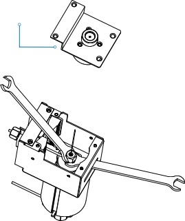
Lower Nut Assembly: Unscrew the 4 screws on both sides to detach the support base, and unscrew the 4 screws at the bottom to remove the bottom cover and the aluminum column;3. Invert the heating element. Use wrench 1 to insert it through the side slot and secure it to the lower hex nut, keeping it steady. Use wrench 2 to grip the hex on the end of the cover plate. Then, insert the other end of the liner into the heating element until it stops at the O-ring. Slide the other new O-ring onto the part of the liner that is now protruding from the heating element, again about 3–4 mm from the port end.

bottom cover assembly wrench 2 Hold one end of the liner that is exposed from the top of the heating element with one hand (to

Loosen the injection needle locking nut and turn it counterclockwise to remove the injection needle (you can use pliers to extract it), then replace it with a new one. (This helps prevent the liner from shifting.) With your other hand, pick up the lower nut assembly and tighten it onto the bottom of the heating element. Tighten


Handle with care during replacement to avoid damaging other components! Place the upper nut assembly on top of the heating element. Insert a new sample septum into the upper


Loosen the nut assembly with a wrench, and then screw on the injection nut. Be careful of the injection needle! Be careful of the injection needle!


upside down
1314
Installation and Replacement of Columns

Installation of a Capillary Column

When installing or replacing a capillary column, the new capillary column is already quite clean and
No additional cleanup is required. However, the column ends should be freshly cut to ensure they are smooth and free of burrs, and to remove any particulate matter from the column, the stationary phase, and the sealing gaskets. These details are very important. Therefore, the column ends should be freshly cut using the ceramic cutting wheel provided in the accessory box by scoring at the point where you want to make the cut. It is common to attach the column nut and gasket before cutting.
Note: Wear protective eyewear to prevent potential eye injuries and skin punctures.
Due to the considerable rigidity of capillary columns, extra care should be taken when handling them, and attention should be paid to personal safety.
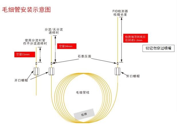
FID Detector Column Insertion Length
When using split or non-split injection
Once you reach the detector end, back up slightly to leave about 80–85 mm (do not extend past the nozzle).
When using a split-line injection tube for non-split injection:
Leave about 20 mm
Leave a 15 mm gap
Graphite Cone Gasket


Graphite Cone Gasket Ferrule Nut



Ferrule Nut

Capillary Column
Ferrule Nut
Pillar Nameplate Pillar Nameplate
Capillary Column Installation Diagram
Capillary columns are shipped from the factory coiled on a metal frame. To install a capillary column, this frame is suspended on the capillary holder inside the GC’s column oven. The position of the holder depends on the diameter of the metal frame. Typically, the capillary column is located in the center of the
column oven of the GC. The ends of the capillary column extend from the bottom of the frame and should be
smoothly curved toward the injector and detector interfaces without touching the walls of the column oven. The capillary column may become contaminated by the graphite ferrule when it is inserted; this can be mitigated by cutting off the top of the ferrule with a razor knife after it has been inserted into the capillary column. The cut
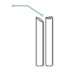
Care should be taken to ensure that it is even and smooth, with no burrs (the left one is OK, but the right one is NG).
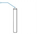
15 Cutting Port OK Cutting Port NG
Installation and Replacement of Columns

Column Installation Steps

① Take a new capillary column, position the column nameplate so it faces you, and hang it on the holder inside the GC column oven.
② Insert one end of the capillary column into a ferrule nut, and then insert a 0.5 mm graphite ferrule with the tapered end facing upward (as shown in the figure below).;

Graphite Cone Gasket

Ferrule Nut
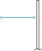
One end of the capillary column, graphite cone gasket, ferrule nut


One end of the capillary column

beforeafter
③ Use a ceramic cutter to cut off 30 to 40 mm from the end of the capillary column that has been fitted with a ferrule nut and a graphite ferrule. Ensure that the cut surface is even and free of burrs or rough edges. If the cut is not perfect on the first attempt, you can make additional cuts as needed.
④ After cutting, align the column with the small hole at the rear end of the injector and insert it approximately 20 mm. Then, slide the graphite ferrule and ferrule nut up and tighten them at the bottom end of the injector using a wrench.
⑤ Follow steps ② through ④ described above to secure the other end of the capillary column, and finally tighten it at the bottom of the detector. The capillary column is now fully installed.
Replace a column

① Columns may be subject to long-term use, aging, or damage, which can result in abnormal peak shapes, unstable baselines, and separation that does not meet requirements. These issues can significantly
affect the analysis results or cause contamination and even damage to the GC or GCMS system.
② When the detection method is changed, it becomes necessary to replace the chromatography column;
③ When the separation of target components is not optimal, it is necessary to replace the chromatography column.
Replacing the column involves steps similar to those for installing it. First, remove the column to be
removed from the GC column oven by loosening the ferrule nuts at the bottom ends of the
injector and detector (this will allow the column to be removed). Then, follow the same steps
Used to install a chromatography column to fit the new one. If the column being replaced has been used before, pay attention to its orientation: the end that was originally connected to the
The injector should be reconnected to the injector, and the end that was connected to the detector
should be reconnected to the detector port. How to tell which end of a used column
Which end connects to the injector, and which end connects to the detector? Generally, this can be determined by the length of the mark left on the column by the graphite ferrule at each port:
If the distance from the port to the impression is approximately ②0 mm, that is the end that connects to the injector.
If the distance from the port to the impression is approximately ⑧0 mm, that is the end that connects to the detector.
of the chromatography column. 16 By correctly identifying and reconnecting each end, you will have completed the replacement.
Instrument Installation Instrument Installation


3. Installation Site Space (for reference only) 1. Gas Source Installation
The gas source should be installed in a safe location, preferably near the GC. It is recommended to use stainless
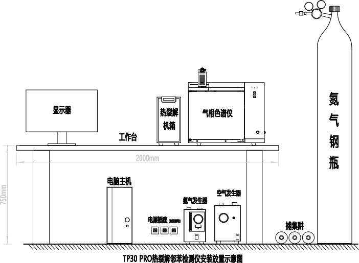
Minimum installation space: 3000 mm (W) × 3000 mm (D) × 2800 mm (H); Recommended workbench: 2000 mm (W) × 700 mm (D) × 750 mm (H) (strong and stable enough); A distance of at least 500 mm is recommended between the workbench and the wall to facilitate equipment cooling, personnel installation, and subsequent maintenance of steel gas lines, and to ensure the proper installation of pressure regulators, ball valves, and other necessary components on the gas lines.


For other types of gas sources (such as gas generators, cylinder gas sources, air compressors, etc.), it is essential to carefully check the quality of the gas produced to ensure it meets the requirements. Otherwise, it may affect the
4. Installation diagram (for reference only)—failure to follow these instructions may affect analysis results or cause contamination and even damage to the GC!
Nitrogen Cylinder: Generally, gas cylinders are used, and they must be secured to prevent them from tipping over and causing accidents. The installation steps for the pressure valves are as follows:
Pyrolyzer Gas Chromatograph 1. Remove the low-pressure outlet heads from the two oxygen pressure valves and one hydrogen pressure valve, attach the regulator connectors, and screw on the low-pressure output adjustment rods without tightening them for now;
Monitor 2. Mount the pressure valves onto the cylinders, tighten the caps, and then open the high-pressure cylinder valves. The high-pressure gauge on the pressure regulator should show some pressure;
Workbench 3. After closing the high-pressure cylinder valve, the reading on the pressure regulator’s high-pressure gauge should not drop. If it does, there is a leak that must be fixed before use can continue.
For the installation and connection of the external gas lines, please refer specifically to the “Electrical and Gas Line Connection Schematic Diagram.”

AirHydrogen Generator Installation Precautions:

1. The gas outlets for the pneumatic circuit and the detector should be connected to pipes that
Vent the gases outdoors to prevent indoor air pollution when analyzing toxic and harmful substances.
Trap 2. During actual operations, be sure to conduct regular leak checks. If a leak occurs, at best it can disrupt the normal operation of the instrument, and at worst, it can lead to accidents (for example,
Computer Case (a hydrogen leak could potentially cause an explosion)
Trap 3. Adjust the carrier gas pressure for the GC to 0.5 MPa;
4. Adjust the air pressure to the GC to 0.5 MPa;
5. Grounding Guidelines: To ensure the safe and reliable operation of the instrument, it is crucial to have a proper grounding method in place. Generally, most countries and regions require the installation of a grounding wire for electrical equipment to ensure personal safety. According to safety standards, electrical equipment must be installed with a safety conductor for grounding. The safety conductor must be connected to the conductive surfaces of the electrical equipment that operators may come into contact with, or to conductive surfaces that could become energized due to electrical accidents. Under normal operating conditions, this wire should not carry any returning alternating current. If the instrument’s frame is not grounded, or if the live wire accidentally comes into contact with the frame, the voltage on the frame could reach a level that poses a significant hazard. Grounding the safety wire to the chromatograph’s chassis can prevent the risk of electric shock. The safety grounding wire in the chromatograph is typically connected to the building’s conduit through an insulated grounding device, and in all cases, it must comply with local and national safety standards. We recommend using a noise-free grounding device. This type of grounding is also known as “insulated grounding” because it is separate from other electrical grounding devices in the building. When connecting the gas chromatograph to other instruments, using “insulated grounding” can help maintain system reliability. This is because, in most cases, standard grounding will inevitably introduce some noise caused by poor grounding (noise may also originate from radio frequency transmitters). 185. Adjust the hydrogen pressure for the GC to 0.5 MPa; Gas line leak check:

After the external gas lines are installed, it is essential to perform a leak test to prevent accidents.
Follow these steps to check for leaks:
Close all the carrier gas steady-flow valves, as well as the hydrogen and air needle valves on the main unit;
Set the cylinder’s low-pressure regulation lever to the relaxed position, open the cylinder’s high-
pressure valve, and then slowly adjust the low-pressure control lever until the low-pressure gauge reads 0.5 MPa;
Close the cylinder’s high-pressure valve. The reading on the low-pressure gauge of the pressure regulator
It should not drop. If it does, there is a leak in the external gas lines, and a thorough inspection is necessary to identify and repair the leak.
2. The equipment should be installed in a clean indoor environment, away from direct sunlight, dust, noise, and gas pollution.
The indoor ambient temperature should be between 5°C and 35°C, with relative humidity not exceeding 85%.

Avoid violent vibrations and frequent movements, strong air currents, and corrosive substances.

The power supply should be AC 220 V ± 22 V with a frequency of 50 Hz ± 1 Hz, and the electrical connection must be grounded.

Since the gas chromatograph is a high-power piece of equipment, it is essential to provide a dedicated power connection and not share it with other devices.

If the power supply is unstable or the voltage fluctuates significantly, it is recommended to use an AC

17 UPS units rated at over 4000 W and an electronic voltage stabilizer.
RoHS Phthalates Testing Procedure Installation Environment Requirements


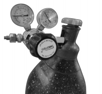
1.1 Power-On and Power-Off Sequence 1.1.1 Turn on the nitrogen cylinder. The gas pressure is 0.4 MPa, and the gas capacity is 8. Grounding methods:


1. Use a wire of the appropriate size to connect to the building’s main pipeline or to the entry point of the main conduit.
2. Drive a long grounding stake into the damp soil and connect it to the entry point.

3. Connect to other reliable entry points.
Adjust the gas pressure to 0.4 MPa
It is generally understood that the ground wire impedance returning to the main

Total pressure gauge for monitoring gas consumption. Turn the valve handle counterclockwise to open the nitrogen supply. The resistance between the grounding bus bar and any load must be less than 11 ohms. The insulated ground wire
must be securely fastened to the device. Do not use clips to attach the ground wire to
pipes or grounding terminals, nor use any other method that could loosen the connection. Minimize the reduction in insulation resistance at the grounding connection points as
as much as possible. If installed improperly, resistance can be measured at the connection
lpoints, and the addition of resistance in the ground wire can create an unwanted potential on the insulated grounding device. When installing the ground wire, prevent it from
accidentally coming into contact with other ground wires, which could adversely affect the insulation.
Note: When the gas level is below 2, this indicates that the nitrogen level is low; the gas cylinder should be replaced immediately!
1. 1.2 Turn on the Hydrogen/Air Generator
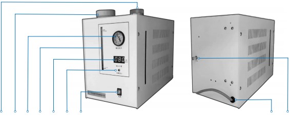
① ② ③ ④ ⑤ ⑥ ⑦ Front Hydrogen Generator Back ⑧ ⑨


| ① Hydrogen Purifier | ④ Electrolyte Water Level Line | ⑦ Power Switch |
| ② Electrolyte Storage Tank | ⑤ Hydrogen Digital Flow Meter | ⑧ Power Cord |
| ③ Pressure Gauge | ⑥ Electrolysis Indicator Light | ⑨ Hydrogen Output Port |
Note: Prepare the electrolyte solution once every six months. In a beaker, add 500 ml of distilled water and weigh out approximately 200 g of potassium hydroxide (KOH, analytical grade). Gradually and slowly add the KOH to the distilled water, ensuring it dissolves.
completely. After the solution has cooled, pour it into the storage tank and top it off with
distilled water up to the maximum water level mark.
19 20
RoHS Phthalates Testing Procedure RoHS Phthalates Testing Procedure


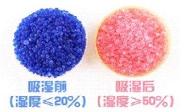
Caution: Potassium hydroxide (KOH), whether in solid form or dissolved in liquid, is highly corrosive and poses a significant risk of injury. Always wear gloves when preparing the solution and take care to prevent it from splashing into your eyes. 2. Please replace the silica gel when it changes from blue to pink. After turning off the instrument, open the exhaust port to release the gas. When the pressure reaches “0,” unscrew the entire silica gel tube counterclockwise. Pour the pink silica gel particles into a beaker, and dry them in a drying oven at 120 degrees Celsius for about two hours until the silica gel turns blue again. 1. 1.3 Turn on the computer. Ensure that the computer’s power cord is properly connected.
connected to the USB data cable, the heating element, and the gas lines of the gas chromatograph.
1. 1.4 Turn on the Pyrolyzer
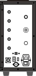
Ensure that the Pyrolyzer’s power cord is properly connected to the computer, the USB data cable, the heating element, and the gas lines of the gas chromatograph.
.
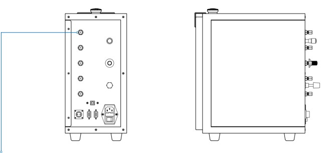

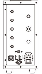
AB
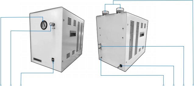



① ② ③ ④ ⑤ ⑥ ⑦ ⑧ ⑨ ⑩

Pyrolyzer SideBack



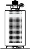
① ② ③ Front Air Generator Back ④ ⑤ ⑥ ⑦① Pressure Gauge③ Power Switch⑤ Power Cord② Pressure Regulator④ Automatic Drain Pipe⑥ Air Outlets (2 sets)⑦ Filters (2 sets) Note: The power switch for the thermal desorption system is located on the back of the chassis (as indicated by in the diagram above).


Before turning on the power, please make sure the computer is already turned on to prevent the thermal desorption system from emitting an alarm beep.
1.1.5 Turn on the Gas Chromatograph (GC)
When the GC is connected to a power source, press the power button located at the

Press the button located at the bottom right of the front panel toward the inside. The power button indicator light will come on, turning on the gas chromatograph.
22
RoHS Phthalates Testing Procedure RoHS Phthalates Testing Procedure


1. 2 Open Gas Chromatography Workstation Software

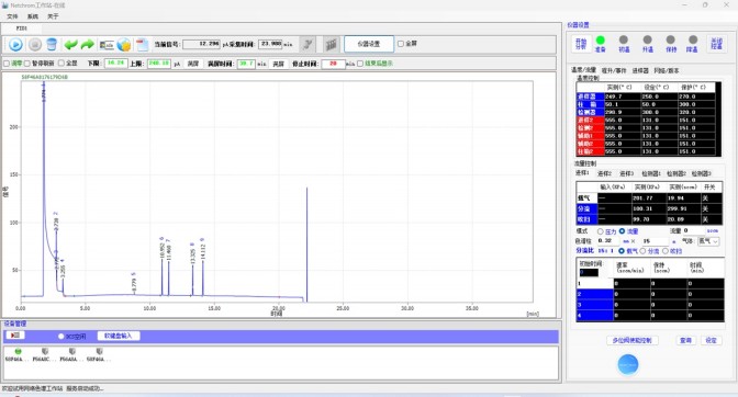
KINY LL Guangzhou Jingu Keji 1.2.2 Open “NetCh rom Online” (as shown below) 1.2.1 Locate the “NetCh rom Online” icon and double-click to open it.





 |
 |
– Remote Rate Final Temp – O O O Start Prep Run Stop Power |
– Remote Rate Final Temp – O O O Start Prep Run Stop Power |
– Remote Rate Final Temp – O O O Start Prep Run Stop Power |
– Remote Rate Final Temp – O O O Start Prep Run Stop Power |
||
  |
– Remote Rate Final Temp – O O O Start PrepRun Stop Power |
– Remote Rate Final Temp – O O O Start Prep Run Stop Power |
|
  |
– Remote Rate Final Temp – O O O Start Prep Run Stop Power |
– Remote Rate Final Temp – O O O Start Prep Run Stop Power |
|
  |
– Remote Rate Final Temp – O O O Start PrepRun Stop Power |
– Remote Rate Final Temp – O O O Start Prep Run Stop Power |
|
  |
– Remote Rate Final Temp – O O O Start Prep Run Stop Power |
– Remote Rate Final Temp – O O O Start Prep Run Stop Power |
|
  |
– Remote Rate Final Temp – O O O Start Prep Run Stop Power |
– Remote Rate Final Temp – O O O Start Prep Run Stop Power |
|
  |
– Remote Rate Final Temp – O O O Start Prep Run Stop Power |
– Remote Rate Final Temp – O O O Start Prep Run Stop Power |
|
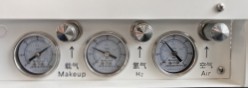
GC Power On Button Pressure Gauges
Notes: Check the three pressure gauges on the lower right side of the gas
chromatograph (as shown in the upper-right figure). The carrier gas should be at
0.3 MPa, hydrogen at 0.1 MPa, and air at 0.15 MPa. If there is no pressure or you are unable to adjust it, please consult a professional or the equipment manufacturer for assistance.
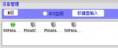
1.2.3 After a moment, on the main interface of the “NetCh rom Online” software, at the
In the bottom-left corner under “Device Management,” a green sphere icon will light up, indicating that the computer is successfully connected to the gas chromatograph (a gray sphere icon
(indicates disconnection). Double-click this sphere icon, and the operating parameters of the gas chromatograph will be displayed in the functional area at the top right of the
software .
2423
RoHS Phthalates Testing Procedure

1.2.4 Check whether the parameters for the chromatograph in the top-right function area of the
The detection software settings are correct: ‘Injector at 250°C’, ‘Column Oven at 50°C’, ‘Detector at 250°C’
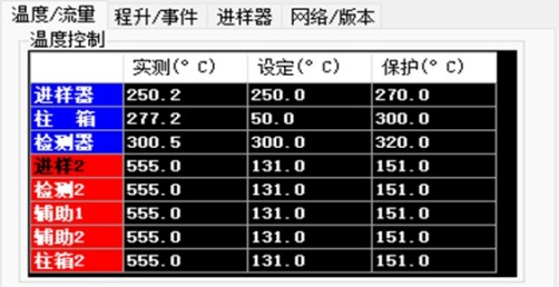
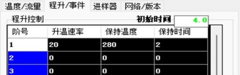
1.2.5 Click the “Start Temperature Control” button on the far right of the parameter area, and the gas chromatograph will begin its temperature programming.
25
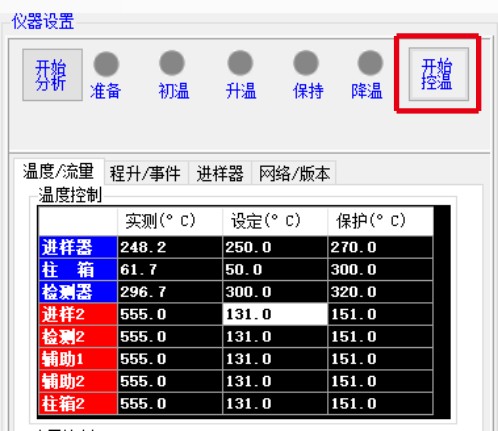
RoHS Phthalates Testing Procedure

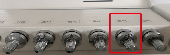
1.2.6 While the program-controlled temperature increase is in progress, adjust the hydrogen valve handle located at the top rear of the gas chromatograph by turning it counterclockwise to the position marked with the red number 6 (the number 6 is red, and the number 0 is black).
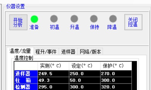
1.2.7 Wait for the temperatures of the injector, column oven, and detector of the gas chromatograph to reach the set values. Once they have reached the set temperatures,
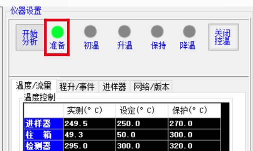
The “Prepare” sphere icon in the parameter area will light up, changing from gray to green.
1.3 FID Detector Ignition
When automatic ignition occurs, you will hear a faint popping sound. When the
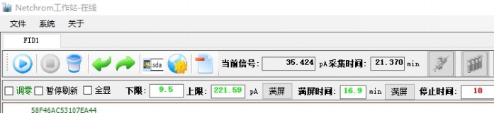
If the “Current Signal” box at the top of the software’s main interface shows an increase in the signal value to 80–300 pA, this indicates that ignition was successful. After ignition, turn the hydrogen valve handle clockwise to reduce the flow by 4–5 turns,
until the signal value is approximately 20–30 pA.
26
RoHS Phthalates Testing Procedure

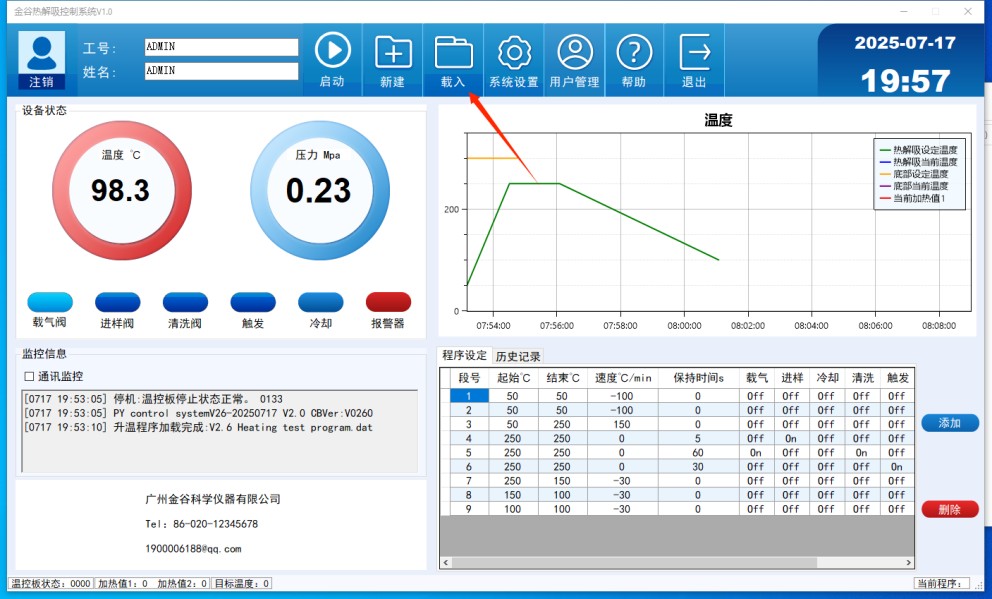
1.4 OpenLISUN Thermal Desorption Control System
1.4. 1 Double-click to open the software

1.4.2 Click the “Load” button at the top and select the required test program.
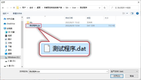
1.4.3 In the pop-up Open dialog box, double-click the “Test Program” folder, locate the “Test Program.dat” file, and double-click it to open it and load the test program.
27
RoHS Phthalates Testing Procedure

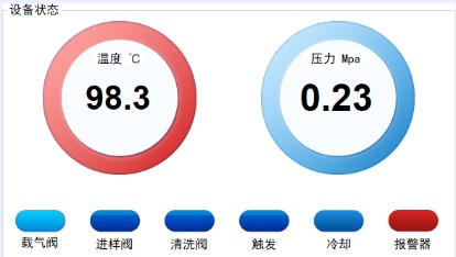
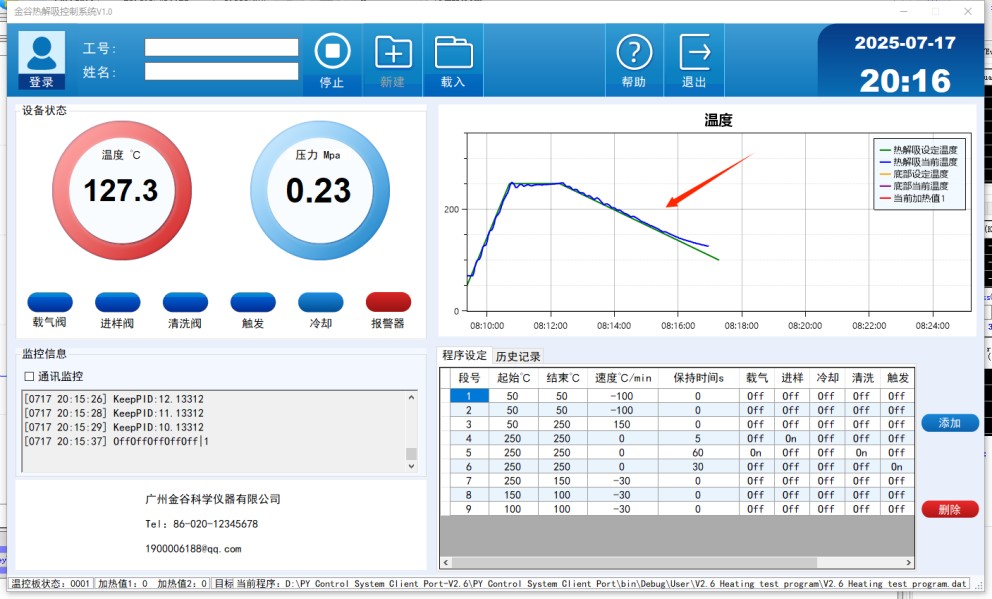
1.4.4 After the test program has been loaded, verify that, on the main interface of the thermal desorption control system, the temperature reading in the “Equipment Status” section is below 60°C, and the pressure reading matches the setting adjusted by the field engineer.
1.4.5 Open the main interface of the thermal desorption control system. Once the system is
If it is running normally, minimize it temporarily. Then, return to the gas chromatography workstation software interface to perform operations related to sample introduction.
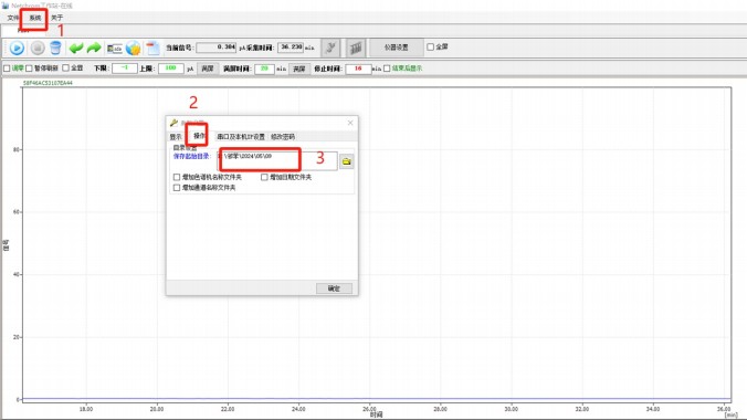
1.4.6 Set up the spectrum save folder for the current day.
28 Return to the “NetChrom Online” main interface, click “System,” then “Options,” followed by “Operations,” and finally “Save Start Directory.” Create a new folder with the current date and click “OK.”
RoHS Phthalates Testing Procedure

1.5 Test Procedure
Once all the preparatory work is completed and everything is ready, the first step is
Conduct a cleaning test, followed by a standard sample test. After the standard sample test and subsequent cleaning, proceed with the
sample testing.
1. 5. 1 Liquid Sample Preparation
1. 5. 1. 1 Sample Size
Cleaning test: 5 µL n-hexane
Standard solution test: 1 μL of 4 P standard
Sample test: 0.5–1.5 mg of a non-viscous sample
or 0.5–1.0 mg of viscous sample
| 1.5. 1.2 Standard Sample Preparation: Preparation List as follows: A. n-hexane or anhydrous ethanol C. standard soliton (consumable) E. coarse quartz wool (consumable) G. quartz sample tube (consumable) I. weighing paper (consumable) K. electronic balance | B. 1 beaker D. 1 micropipette F. small quartz wick (consumable) H. special sample cutter J. tweezers |
29
RoHS Phthalates Testing Procedure

① First, remove the micropipette and rinse it in n-hexane at least five times. Continue rinsing
“until there are no bubbles inside the micropipette.”
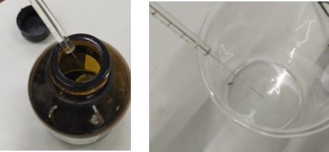
Note: The liquid used for rinsing should not be returned to its original container. Instead, it should be poured into a designated beaker and disposed of at the end of the workday.
② After cleaning, use the pipette to rinse it with the standard sample reagent at least five times, making sure there are no air bubbles inside the pipette. Only then should you aspirate 1 µL of
the reagent, specimen, or sample. Keep the micropipette horizontal.
Keep it horizontal
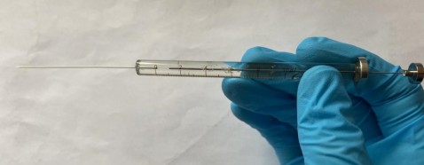
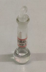
Note: The liquid used for rinsing should not be returned to its original container. Instead, it should be poured into a prepared beaker and disposed of at the end of the workday.
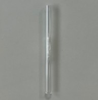
③ Take a quartz sample tube and use tweezers to place a small amount of quartz cotton in the middle section of the tube. Then, inject the liquid specimen obtained in “Step 4.2.2.2” into
30th
RoHS Phthalates Testing Procedure

1.6 Testing Procedure
1.6.1 Single-sample testing
① Wait for the circular “Prepare” icon on the main interface of the “NetChrom Online” workstation software to turn green
② Place the quartz sample tube prepared in step “1.5.1.2” into the heating head. Put on the
Remove the septum for sample introduction, then replace the sampling cap and tighten it appropriately (for the correct tightness, refer to the maintenance guide at the back of this manual— > Item 2 regarding the gas chromatograph)
Small quartz tube sample → sample inlet septum → screw cap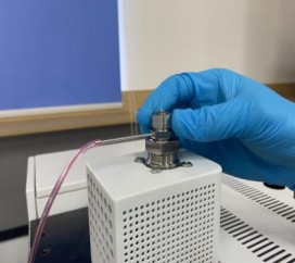   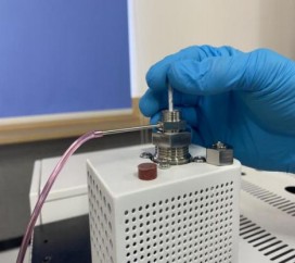 |
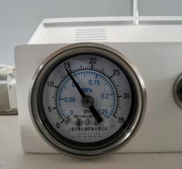
③ Check the pressure gauge for the column head pressure on the rear top of the gas
chromatograph. Ensure that the “column head pressure” value returns to a stable value.
31
RoHS Phthalates Testing Procedure

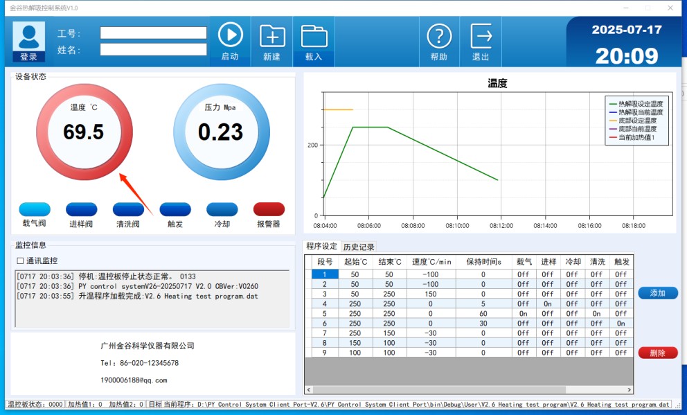
④ On the main interface of the “LISUN Thermal Desorption Control System” (where the set temperature is displayed as a green curve), ensure that the temperature of the heating head
does not exceed 70°C, and at the same time, verify that the pressure reading is stable.
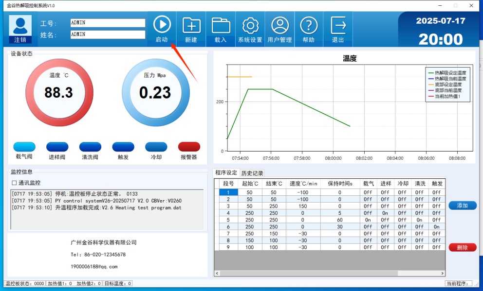
⑤ On the main interface of the “LISUN Thermal Desorption Control System,” click “Start.”
32
RoHS Phthalates Testing Procedure

Prerequisite: If a single sample does not exceed the standard, continuous sampling may be performed. After clicking “Start,” the program begins to run, and the temperature control curve is displayed in
e, the figure below. The blue “Current Temperature” curve should follow the “Set Temperature” curve, and the fluctuation should be minimal.
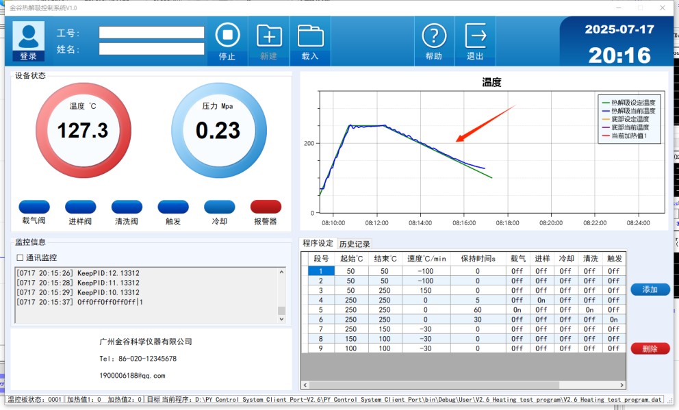
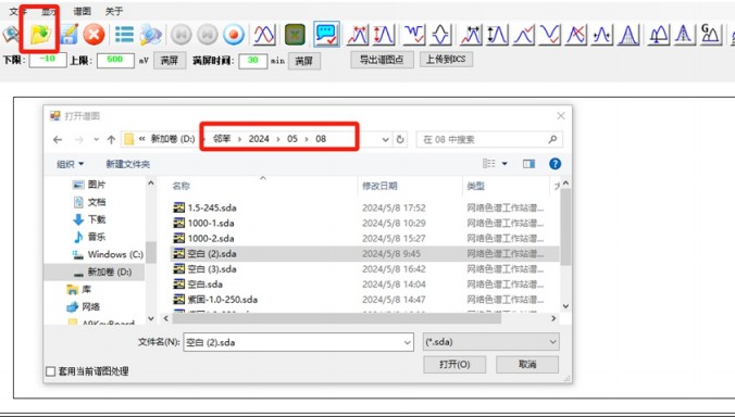
⑥ After the test is complete, locate the “NetChrom Offline” workstation software, double-click to open it, and then click “Open” on the main interface. Follow the save path to locate the tested
33spectrum and name it ‘(Sample Name + Sample Weight)’
RoHS Phthalates Testing Procedure

1.6.2 Continuous Sampling
① Instrument Preparation: Ensure that the temperature of the thermal desorption control system is below 60°C; in the “NetChrom Online” workstation software, click the “Prepare” sphere icon on the
The main interface should be lit up in green.
② Testing: Repeat the process described in step 1.5
③ When 5 consecutive samples all pass the test without exceeding the limits, a cleaning test must be performed once. If any one sample exceeds the limit, a cleaning test must be conducted and
Repeat this process until the residue is completely clean before proceeding to the next sample.
Solid Sample Sampling & Testing

2.1 Sample Cutting and Weighting
Principle: Take samples at multiple points, using small quantities each time.
Use a sample-specific knife and collect small amounts of samples from different locations.
There should be at least five sampling points, and the total sample mass should be between 0.5 and 1.5 mg.
“When sampling sticky or soft materials, the sample size should be between 0.5 mg and 1.0 mg.”
“Always wear gloves when taking samples to prevent contamination and ensure that the experimental results are not affected.” “Place samples directly on the weighing paper.”
:
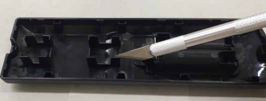
2.2 First, use a calibration weight to adjust the scale. During calibration, make sure the water droplet is centered. After sampling, weigh the sample.
34
Solid Sample Testing

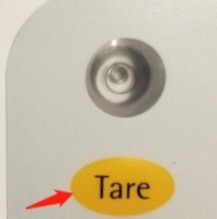
2.3 First, weigh the weighing paper, then press the tare button “T” (indicated by the red arrow in the diagram above). Next, place the sample on the weighing paper and weigh them together. The final number displayed will be the weight of the sample plus the weight of the weighing paper.
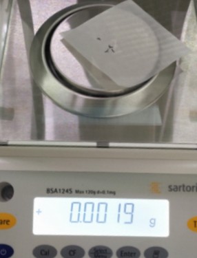
To ensure accurate weighing, please follow these guidelines:
Avoid any strong air currents or drafts near the scale.
Place the sample exactly in the center of the weighing tray.
Keep the tray clean and tidy.
Any deviation from these conditions could compromise the weighing process.
results.
2.4 After weighing, place the sample in the middle section of the quartz sample tube and seal both ends with quartz cotton, as shown below:
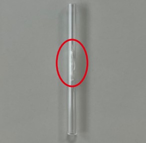
Tip:
Use tweezers to hold a small amount of quartz wool to seal one end of the quartz tube first, then place the test sample inside, and finally use
Use tweezers to hold a small amount of quartz cotton to block the other end. This method helps prevent solid
samples from being blown into the instrument.
2.5 Testing
35 Repeat steps 1 through 5
Standard Solution Data Processing

3.1 Create a component table and construct a calibration curve. Open and rename the standard solution file for the current day.
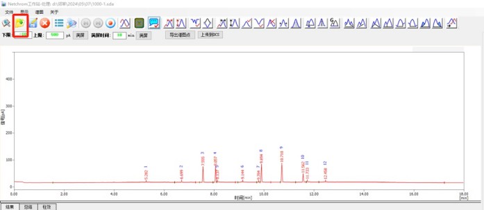
Note: This step must be completed after the standard solution testing is finished and before the first sample test is conducted.
3.2 Integration of Standard Solutions
Click “Delete Peak” to remove all peaks; then click “Add Peak” to integrate the peaks for DI BP, DB P, BB P, and DE HP; and finally click “Save” (as shown below).
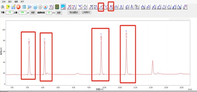
3.3 Create a new component table
36Click “File,” then select “Edit Component Table” (as shown below)
Standard Solution Data Processing

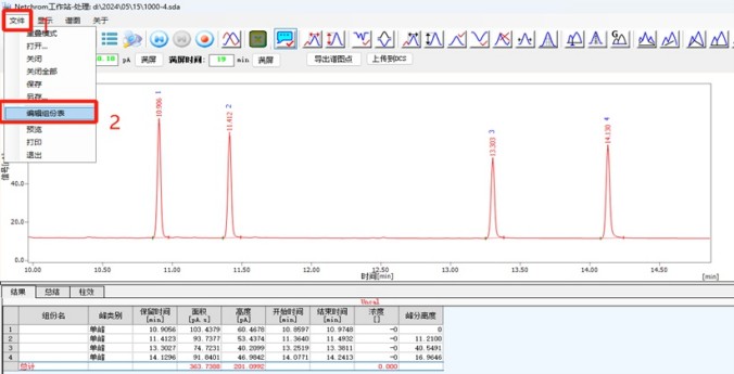
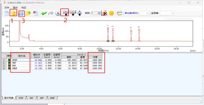
In the pop-up window, open the integrated standard solution spectrum, then click “Open”
In the ‘Component Table’, select the 4p. cal file, and choose ‘Add All Peaks’. Verify that the component names (DI BP, DB P, BB P, DE HP) are correct and that the concentration is 1000 ppm. Click ‘Save’ to complete the standard solution processing.
37
How to Generate the Test Report

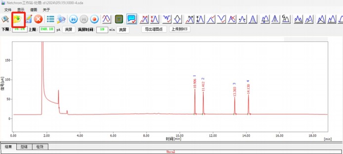
4.1 Open the spectrum of the processed standard solution. (As shown in the figure below.)
4.2 Spectrum Overlay
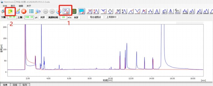
Click on “Spectrum Overlay,” open the folder, and overlay the sample spectrum.
4.3 Delect Peak
38Click “Delete Peak” to remove all integrals from the sample spectrum.
How to Generate the Test Report

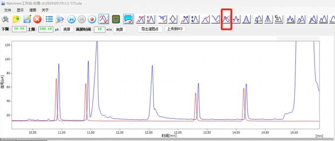
4.4 Add Peak
“Click ‘Add Peak’ to integrate the four peaks that overlap with the phthalate 4P standard solution, then click ‘Save’.”
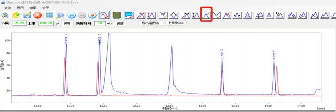
4. 5 Click on “Quantitative Result Calculation,” then select “Quantitative Component Table File,” open the 4pcal file, and confirm.
39
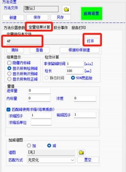
How to Generate the Test Report

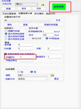
4.6 To calculate the sample content, go to “Quantitative Result Calculation” and then to “Concentration Factor.” Enter the sample mass and click “Apply Settings.” As shown below
4.7 Print Report
After reviewing the sample test results, click “Save” and then print the report.
40
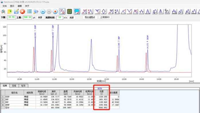
Power-Off Process

5.1 Turn Off Temperature Control
In the “NetChrom Online” software, on the main interface, click the “Instrument Settings” panel located in the upper-right corner, and select “Turn Off Temperature Control.” Wait until
The temperature drops below 100 degrees (as shown in the figure below).
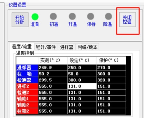
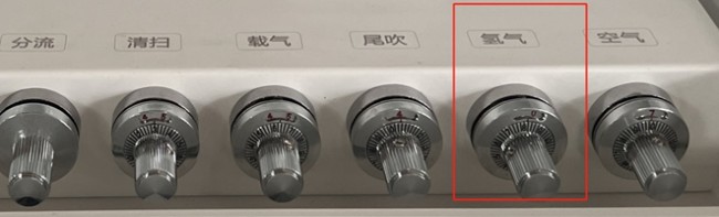
5.2 Turn Off the Hydrogen Supply
Turn the hydrogen valve handle counterclockwise to the 0 position, and the signal value should display as “0 ” (as shown in the figure below).
5.3 Turn Off the Gas Chromatograph
When both the injector temperature and the detector temperature are below 100°C, press the power button on the front panel.
5.4 Turn off the Pyrolyzer
41 Boat-shaped power switch on the back of the case
Power-off process

5. 5 Turn off the Air Generator
Power Butter in the front
5. 6 Turn off the Hydrogen Generator
Power Butter in the front
5. 7 Turn off the nitrogen cylinder
Warranty Notice

In order to better serve our valued customers, our company hereby commits that all

The products and accessories provided are of good quality and meet the product’s functionality and requirements. The product warranty period is one year from the date of acceptance following delivery. We will provide free software upgrades if the product hardware is still in good
condition .
Warranty Terms: After the product is delivered and put into use, if defects occur repeatedly,

We will provide an analysis report and a solution until the final correction is made. The one-year warranty period for the corrected parts will be recalculated from the date of correction.
Response Time: During the warranty period, upon receiving an urgent request for warranty service from a customer, we will arrive on-site within 24–48 hours. If the defect affects normal operation, our company will promptly replace the defective unit with a spare to

ensure the customer’s normal operations.
After-Sales Service Information

| Customer | Phone | ||
| Address | |||
| Supplier | |||
| Product | |||
| Model | Purchase Date | ||
| Service Technician | Set Date |
42
Maintenance and Care Fault Analysis and Troubleshooting


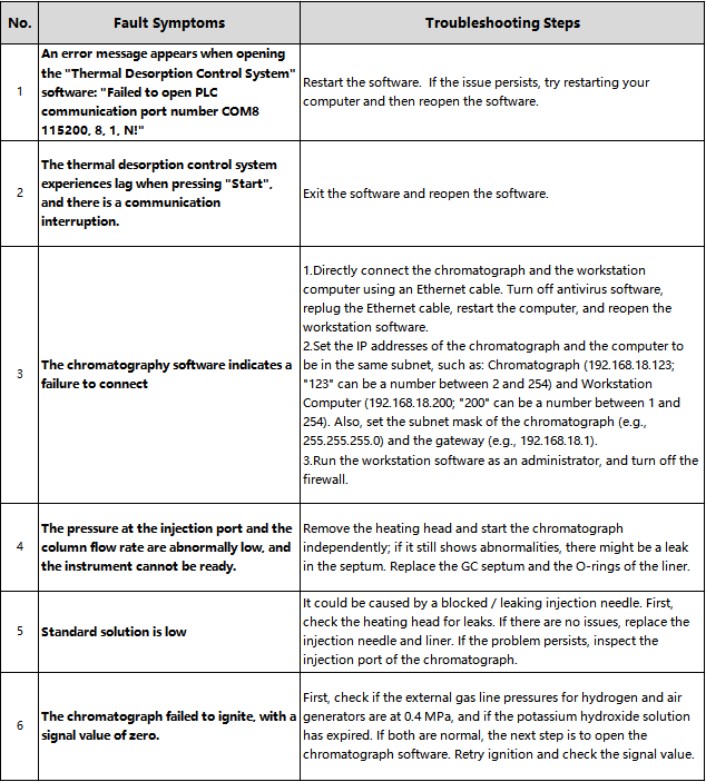


| Item | Maintenance Checklist |
| Gas Chromatograph | 1. Equipment Aging: With the equipment operating normally, load the “Aging” method and perform routine aging for 4 hours. After the aging process is complete, reload the “4P” method. 2. Chromatography Injection Septum: It is recommended to replace the septum regularly, typically once a month. Excessive use of the septum can cause debris to fall into the liner. Tighten the septum nut by hand, then loosen it by 60 degrees; there should be a 1 mm gap between the crescent-shaped piece above the septum nut and the nut itself. If the septum is too tight, it will produce debris prematurely; if too loose, it may lead to air leaks. 3. GC Injection Port Liner: Replace the liner regularly on a weekly basis. It can be ultrasonically cleaned and reused. Replace the liner when it becomes dirty, or if there are signs of debris, black contaminants, transparent crystalline salts, or poor sample repeatability. Secure the liner’s nut with a wrench without overtightening to avoid crushing the liner. The quartz cotton should not be packed too tightly; keep it fluffy. 4. FID Nozzle (Ignition Port): A clogged nozzle can cause abnormal peaks or ignition difficulties. To resolve this, remove the nozzle and clean it with a fine wire to remove blockages. However, frequent disassembly and cleaning are generally not necessary. 5. Used Quartz Tube: After removing the quartz cotton, clean the quartz tube ultrasonically with n-hexane; repeat this ultrasonic cleaning process six times and dry the tube thoroughly. 6. Split-Flow Trap: Replace the activated carbon every two weeks. After replacement, the activated carbon can be reused. It is installed at the split and septum purge gas outlet of the injection port and effectively adsorbs organic samples from the carrier gas, preventing sample condensation in the subsequent pipeline that could lead to blockages. Loosen the nuts at both ends with a wrench and insert fresh activated carbon. 7. Carrier Gas Trap (Oxygen, Hydrocarbon, and Moisture Removal): With a capacity of 750 cm³, the trap typically lasts for 2 years. It is used for gas purification inside the gas chromatograph. The trap is for single use only and should not be reused. 8. Liner O-Ring: Replace it when the gas chromatograph’s airtightness is compromised, and replace it routinely every six months. |
| Pyrolyzer | 1. Heating Element Liner: Clean it every 2–3 days: Clean the inner wall of the liner 2–3 times using a cotton swab dipped in n-hexane. Replace the liner every 2 weeks. The liner can be reused after ultrasonic cleaning with n-hexane. 2. Injection Needle: Replace it once a week. 3. Large Nut on Heating Element: Clean it once a week using a cotton swab dipped in n-hexane. 4. Large Nut Below the Heating Element: Clean it once a week by first wiping it with a cotton swab dipped in n-hexane, then ultrasonically cleaning it with n-hexane for 5–6 cycles. 5. Liner O-Ring: Replace it when the thermal desorber’s airtightness is compromised, and replace it every 6 months. 6. Graphite Paper: Replace it when it is damaged. |
| Hydrogen Generator | 1. Electrolyte Solution Preparation: Prepare the solution every 6 months. In a beaker, gradually add 200 g of potassium hydroxide (KOH, analytical grade) to 500 mL of distilled water in small amounts, allowing it to dissolve slowly. After complete dissolution and cooling, transfer the solution to the storage tank and top it off with distilled water to the maximum water level. Wear gloves during preparation to prevent skin irritation and take care to avoid splashing the solution into your eyes. 2. Silica Gel Replacement: Replace the silica gel when it changes from blue to pink. Turn off the equipment, then open the exhaust port to release the gas until the pressure reaches “0.” Unscrew the tube counterclockwise and place the pink silica gel in a beaker; then place the beaker in an oven at 120 degrees Celsius for about 2 hours until the silica gel turns blue again. |
| Air Generator | 1. Activated Carbon: The built-in dual activated carbon filters should be replaced (500 g at a time) after approximately 500 hours of continuous use or approximately 3 months of intermittent operation. Turn off the equipment, then open the exhaust port to release the gas until the pressure reaches “0,” and unscrew the filter counterclockwise. |
4443
Warranty and Repair

Repair History

| Date | Troubleshooting and Maintenance Guide | Customer | Signature | Service Technician | Signature |
45
Disclaimer


1. LISUN reserves the right to interpret and correct any printing errors in this manual. Changes to the materials resulting from product upgrades or updates will not be notified.

separately and will be directly included in the new version of the manual.
2. This user manual is as comprehensive and detailed as possible based on the available materials; however, LISUN reserves the right to modify the

The product’s colors, specifications, and other information. Any changes will not be notified separately.
3. There may be differences between the product information in this user manual and that of the actual product. Please refer to the actual product.

4. Users must strictly follow industry standards when using the product. Any injury or consequences resulting from incorrect use or improper operation of the product—not attributable to the product itself—shall be the responsibility of the user.

5. LISUN INSTRUMENTS LIMITED shall not be liable for any personal injury or property damage caused by force majeure or the user’s own gross negligence.

6. LISUN INSTRUMENTS LIMITED is not responsible for any impairment in the product’s functionality resulting from improper use by the user.

such as using external ports (e.g., USB, serial ports, etc.) or installing third-party software to modify or add other functions.
46 Controlled document, for internal use only!
