
 English
 中文简体
中文简体 English
 Русский
 Español
 Português
 Türkçe
 العربية
 Deutsch
 Polski
 Italiano
 Français
 한국어
한국어 ไทย
ไทย Tiếng Việt
 日本語
日本語





























Low-Temperature Impact Device
User's Manual
Applicable LISUN models: DWC-1
1. Basic Understanding of Equipment
1.1 Scope of Equipment Application
The DWC Series Low-temperature Impact Device is specialized testing equipment designed and manufactured in accordance with multiple national and international standards. It is primarily used to test the impact resistance of PVC-sheathed cables, wires, flexible cords, and unsheathed parallel flexible cords in low-temperature environments, and to verify whether the materials’ low-temperature brittleness and impact strength meet the requirements of these standards.
1.2 Applicable Standards
| LISUN Model | DWC-1 | DWC-2 | DWC-3 |
|---|---|---|---|
| Drop Weight | 100 g, 200 g, 300 g, 400 g, 500 g, 600 g, 750 g, 1000 g, 1250 g, 1500 g | 100 g, 1000 g | 0.5 kg, 1.0 kg, 2.0 kg, 6.8 kg |
| Applicable Standards | GB/T 2951.14, Section 8.5 and Figure 2 (IEC 60811-1-4, Section 8.5 and Figure 2), GB/T 5013.1 (IEC 60245-1), GB/T 5023 (IEC 60227-1) | GB/T 2099.1, Section 24.5 and Figure 27, and Section 30.5 and Figure 42 (IEC 60884-1, Section 24.5 and Figure 30, and Section 30.5 and Figure 42), GB/T 17466.1, Figure 21 (IEC 60670-1, Figure 21) | GB/T 20041.1, Section 10.3 and Figure 2 (IEC 61386-1, Section 10.3 and Figure 2) |
Note: This manual uses the DWC-2 as an example.
1.3 Test Principles
1.3.1 Description of Supporting Equipment
This device is a shock actuator and must be used in conjunction with the LISUNG DJW series low-temperature test chambers to meet the low-temperature environmental testing requirements specified in the standards. The low-temperature test chamber provides a stable low-temperature environment; both the shock device and the test specimens must be pre-cooled in this environment.
1.3.2 Test Principle
After holding the test specimen in a specified low-temperature environment for a specified period of time, a specified-weight impact weight is dropped freely from a set height to strike a designated area of the specimen. Following the test, the specimen is inspected for defects such as cracks or breakage, and the material’s low-temperature impact resistance is evaluated based on these findings.
1.3.3 Workflow Logic
Condition the specimen at low temperature → Place the specimen in the impact station → Lock the impact weight at the set height → Release the weight for a free-fall impact → Remove the specimen for inspection → Evaluate the test results
2. Safety Precautions
2.1 Installation Environment for the Equipment
The equipment must be placed on a level and stable test bench with a tilt of no more than 2°;
Leave at least 50 cm of clearance around the area and keep it away from flammable and explosive materials.
2.3 Operational Safety Guidelines
Operators must undergo training on this manual and become familiar with the equipment’s structure and operating procedures before being allowed to operate it;
Operators with long hair must tie it back to prevent it from getting caught in moving parts of the equipment;
When operating the equipment, wear cryogenic protective gloves to prevent frostbite from contact with cold test specimens or the inner walls of the cryogenic chamber;
Wear safety goggles to prevent injury to the eyes from flying fragments of the specimen;
Damaged test specimens resulting from the impact must be collected properly to avoid cuts from sharp edges;
It is strictly prohibited to test specimens that exceed the device’s rated load capacity;
The use of non-standard weights or impact distances for testing is strictly prohibited.
3. Introduction to the Device
3.1 Standard Diagram
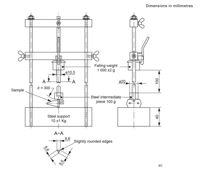
3.1.1 Schematic Diagram of The Low-Temperature Impact Device For Plugs
See Figure 3-1 (taken from IEC 60884-1:2022, Figure 30).
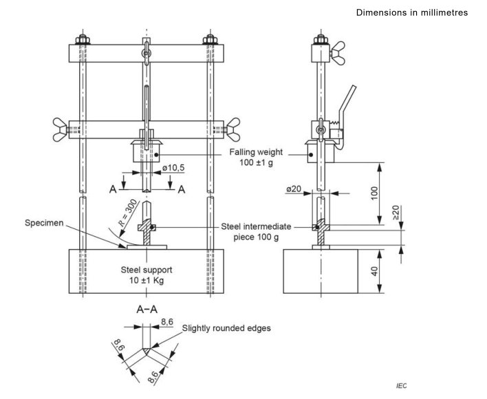
3.1.2 Schematic Diagram of The Low-Temperature Impact Device For Plug Insulation Sleeves
See Figure 3-2 (taken from IEC 60884-1:2022, Figure 45).
3.2 Photographs of the Actual Device
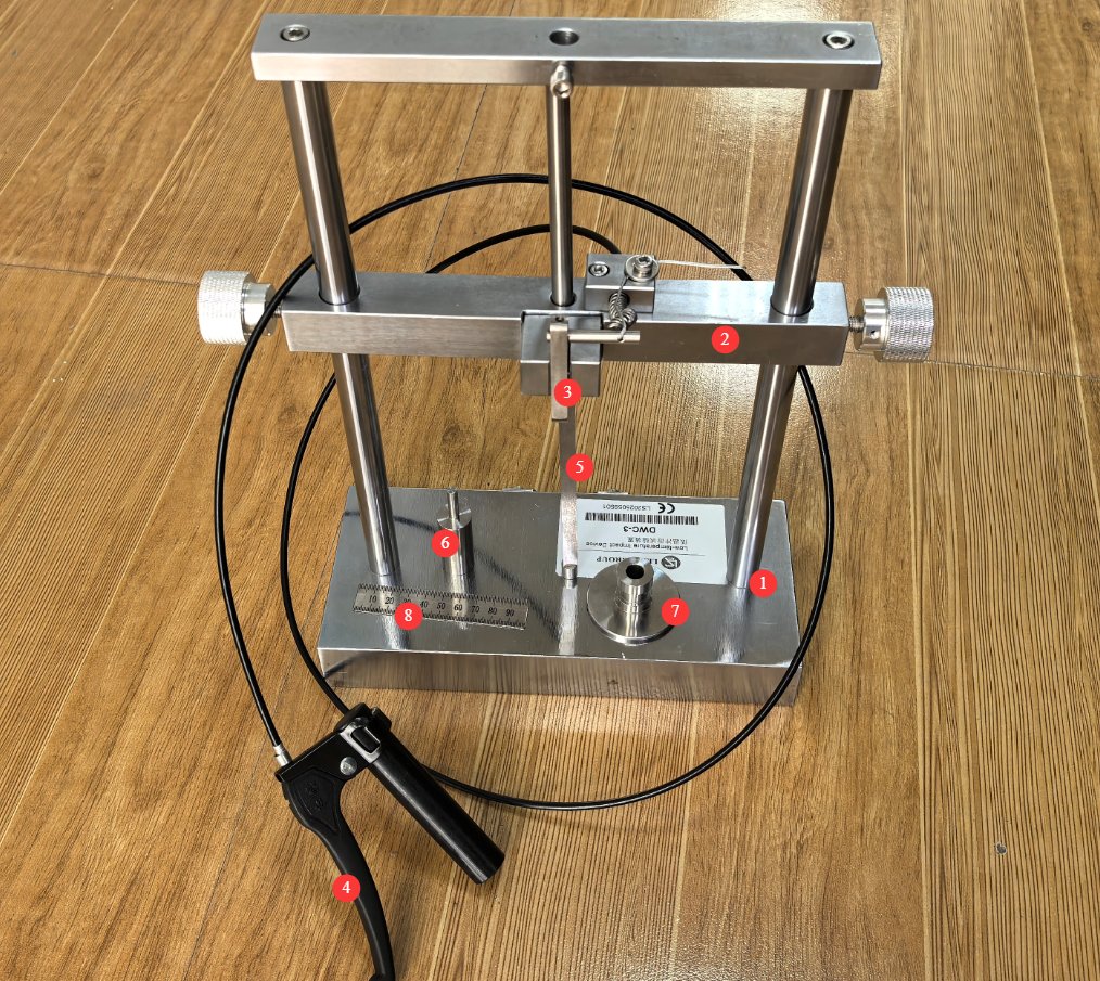
3.2.1 Test Setup Components
See Figure 3-3.
| Number | Note |
|---|---|
| ① | Steel Base and Bracket |
| ② | Adjustable Weight Holder |
| ③ | Weight Locking Device |
| ④ | Release mechanism: Press to release the weight for the impact test |
| ⑤ | Adjustable guide rod used to control the vertical descent of weights and secure steel spacers |
| ⑥ | Steel Spacers for 100g Drop Weights |
| ⑦ | 100-gram drop weight |
| ⑧ | 100-mm steel ruler, to control the impact height |
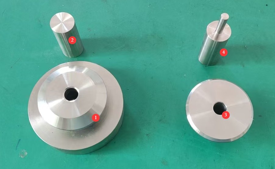
Note: The 1000-gram drop weight comes with a matching steel spacer; see Figures 3-4.
| Number | Note |
|---|---|
| ① | 1000-gram drop weight |
| ② | 1000g Drop Weight with Steel Spacer Block |
| ③ | 100-gram drop weight |
| ④ | Steel Spacers for 100g Drop Weight |
3.2.2 Impact Test Setup Diagram
Taking a 100-gram drop weight as an example—specifically, the low-temperature impact test on the insulated sleeve of a plug as described in Section 3.1.2—see Figure 3-4.
| Number | Note |
|---|---|
| ① | 100g Drop Weight Installation |
| ② | Installation of Steel Spacers |
| ③ | Note: During the test, place the test specimen pin between the steel spacer and the steel base. See 3.1.2. |
| ④ | Use a 100-mm steel ruler to determine the impact height, which is the distance between the falling hammer and the steel spacer. |
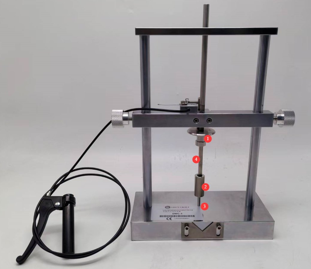
For a 1000-gram drop weight, simply replace ② with the corresponding steel spacer.
4. Low-Temperature Impact Test
4.1 Low-Temperature Impact Test for Plugs
See Clause 24.5 of IEC 60884-1:2022.
Place the test setup, which is positioned on a 40-mm-thick sponge rubber block, along with three intact test specimens, into a test chamber maintained at a temperature of -15°C for at least 16 hours. At the end of this period, place each test specimen in the test position one by one and drop the hammer from a height of 100 mm. The mass of the hammer is 1000 g. After the test, the test specimens shall show no damage within the scope of this document.
4.2 Low-Temperature Impact Test for Plug Insulation Sleeves
See Clause 30.5 of IEC 60884-1:2022.
A device consisting of a 100-gram drop weight placed on a 40-mm-thick sponge rubber pad, together with three intact test specimens, is placed in a test chamber maintained at a temperature of -15°C for at least 24 hours. At the end of this period, place each specimen in the test position one at a time and allow the drop weight to fall from a height of 100 mm. The same test specimen shall undergo four consecutive impacts; between each impact, the specimen shall be rotated 90°. After the test, the specimen shall be allowed to return to approximately room temperature before inspection. Without any additional magnification, the insulating sheath shall be free of cracks visible to the naked eye or with corrected vision.
5. Daily Maintenance and Care of Equipment
Daily Cleaning and Maintenance
5.1.1 Maintenance After Each Test
Wipe the surface of the device with a dry cloth to remove condensation and dust; check the surfaces of the weights, steel shims, and steel base for stains, and wipe them clean immediately.
5.1.2 Weekly Maintenance
Clean the surface of the guide rail with anhydrous ethanol to ensure it is smooth and rust-free; check all fastening screws for looseness and tighten them as needed; check whether the spring in the release mechanism is functioning properly.
Regular Lubrication and Rust Prevention
Apply a thin layer of low-temperature grease to the surface of the guide rail to reduce friction; apply a small amount of lubricating oil to the release mechanism and the areas around the mounting screws; check the stainless steel surface for any signs of rust, remove any rust promptly, and apply a rust-preventive treatment.
5.3 Long-Term Storage and Maintenance
Pre-treatment for Storage
Thoroughly clean and dry the equipment, and apply rust-preventative oil to all metal surfaces; pack and store weights and other accessories separately to prevent damage; cover the entire unit with a dust cover for protection.
Storage Environment Requirements
Store indoors in a dry, well-ventilated area free of corrosive gases; ambient temperature should be between 5°C and 35°C, with relative humidity not exceeding 80%; keep the equipment in a horizontal position to prevent deformation caused by heavy pressure.
5.4 Calibration Interval Requirements
To ensure the accuracy and reliability of the device, it is recommended that it be sent periodically to a qualified third-party metrology laboratory for calibration. The recommended calibration interval is 12 months. Users may determine the specific calibration interval based on frequency of use, environmental conditions, and quality system requirements.
6. Troubleshooting and Resolving Common Problems
| Fault Symptoms | Procedure |
|---|---|
| The drop hammer gets stuck during descent | Use a level to ensure the device is placed horizontally; make sure the guide rail is vertical, remove any dirt or foreign objects from the rail, and check the clearance between the drop weight and the guide rail. |
| Addressing Institutional Failures | Inspect the spring; if it is defective, replace it. If it is sticking, apply a neutral lubricant. If the mounting screws are loose, adjust the release mechanism cable until it is at the proper tension, then retighten the screws. |