
 English
 中文简体
中文简体 English
 Русский
 Español
 Português
 Türkçe
 العربية
 Deutsch
 Polski
 Italiano
 Français
 한국어
한국어 ไทย
ไทย Tiếng Việt
 日本語
日本語





























Automatic Single-Arm Drop Test Machine
User's Manual
Applicable LISUN models: DT-100KG-S、DT-60KG、DT-60KG-D、DT-80KG-D、DT-80KG-S
1. Unboxing and Basic Familiarization with the Equipment
1.1 Key Technical Specifications
| Model | DT-60KG-D | DT-80KG-S | DT-100KG-S |
| Product Name | Double-Arm Drop Tester | Single-Arm Drop Tester | |
| Drop Height | Adjustable from 400 to 1500 mm | Adjustable from 300 to 1500 mm | Adjustable from 300 to 1800 mm |
| Drop Height Error | ±10 mm | ||
| Impact Panel Dimensions | 1700 × 1400 mm | 1700 × 1200 mm | 1700 × 1400 mm |
| Base Plate Thickness | 10 mm (solid steel plate) | ||
| Single-arm plate dimensions | 700 × 350 × 6 mm | ||
| Maximum weight of the specimen | 0–60 kg | 0–80 kg | 0–100 kg |
| Maximum Dimensions of the Test Specimen | 1000 × 1000 × 800 mm | 800 × 800 × 1000 mm | 1000 × 1000 × 800 mm |
| Test Bench Dimensions | 1900 × 1400 × 2315 mm | 1700 × 1200 × 2315 mm | 1800 × 1800 × 2315 mm |
| Net Weight of the Test Bench | 420 kg | 395 kg | |
| Test Method | Comprehensive drop tests on surfaces, corners, and edges; automatic height adjustment; and an LED digital display to eliminate errors caused by human observation. | ||
| Power Supply | Three-phase 380 V, 50/60 Hz | ||
1.2 Unboxing and Checking the Contents
1.2.1 Unpacking and Visual Inspection
When unpacking the device, handle it gently to avoid scratching the outer casing with sharp tools. After unpacking, first inspect the exterior of the device to ensure there is no visible deformation or dents, and that the buttons are not damaged or loose. If you notice any abnormalities with the device or its accessories, do not turn it on; please contact us immediately.
1.2.2 Main Unit and Accessories
DT Series Automatic Drop Testers: 1 unit.
Download links for the electronic user manual, software, warranty card, and other materials have been sent via email. Please download them as soon as possible. If you missed the email, please feel free to contact us to request the download links again.
1.3 Scope of Application
The equipment fully complies with the requirements of the following domestic and international drop test standards, and the test process can be conducted in direct accordance with these standards:
National Standards: GB/T 4857.5-92 (Test Method for Drop Testing of Transport Packaging), GB/T 2423.5 (Environmental Testing of Electrical and Electronic Products—Free-Fall Test), JIS Z 0202-87 (Japanese Standard for Packaging Drop Tests)
International Standards: ISO 2248-1985 (Packaging—Free-Fall Test), ASTM D 5276-1998 (American Standard Test Method for Packaging Drop Tests), IEC 60068-2-27 (Environmental Testing of Electrical and Electronic Products—Impact Testing)
2. Safety Precautions
2.1 Electrical Safety
The equipment’s input power supply is a three-phase AC 380V, 50/60 Hz supply. Ensure that the input power supply matches the specifications on the equipment nameplate. Never connect the equipment to a voltage other than the rated voltage to prevent short circuits or damage to the equipment.
The equipment must be properly grounded. Before testing, check that the grounding terminal is securely connected. Never skip the grounding step, as doing so poses a risk of electric shock or equipment short circuits.
A ground-fault circuit interrupter (GFCI) and a contactor rated for the appropriate capacity must be installed at the power supply input. The GFCI must have a rated current of at least 16 A to ensure that the power supply is immediately cut off in the event of a equipment failure, thereby preventing the accident from escalating.
Before performing equipment maintenance or troubleshooting, you must turn off the power and unplug the power cord to prevent electric shock.
2.2 Operating Procedures
Operators must complete pre-employment training and become familiar with the operating procedures outlined in this manual before operating the equipment. Unauthorized personnel are strictly prohibited from operating the equipment independently.
During the official drop test, only one person is required to operate the control console; all other personnel must evacuate to a safe area.
While the equipment is in operation, do not touch any parts other than the control panel; do not place your head or hands inside the yellow caution line; and do not adjust the clamps or touch the test specimen while the drop arm is rising or lowering.
If you need to move the machine, be sure to turn off the power and let it cool for 5 minutes before proceeding.
It is strictly prohibited to place test specimens that exceed the weight or size limits, and it is strictly prohibited to pile up debris on the impact panel.
If the equipment triggers an alarm, stop the test immediately; if necessary, cut off the power supply immediately, and restart the equipment only after troubleshooting the problem.
2.3 Environment and Protection
The equipment should be used in a dry, well-ventilated environment free of corrosive gases, with an ambient temperature of 0–40°C and relative humidity of ≤85%. Avoid moisture or excessive dust, which can cause equipment malfunctions.
Do not cover the ventilation openings while the equipment is running, and do not place flammable or explosive materials near the equipment.
The test site must ensure an unobstructed space of at least 1.5 meters around the equipment. The ground surface must be level and solid—either concrete or steel—with a load-bearing capacity of at least 500 kg/m². Operating the equipment on soft or sloped ground is prohibited.
2.4 Other
For matters not covered in this manual, please proceed with caution or contact us.
3. Equipment Overview
3.1 Overall Structure of the Equipment
3.1.1 Single-Arm Drop Tester
| No. | Note |
| ① | Control Cabinet |
| ② | Drop Arm, Single Arm |
| ③ | Specimen Clamping Fixture |
| ④ | Base Plate |
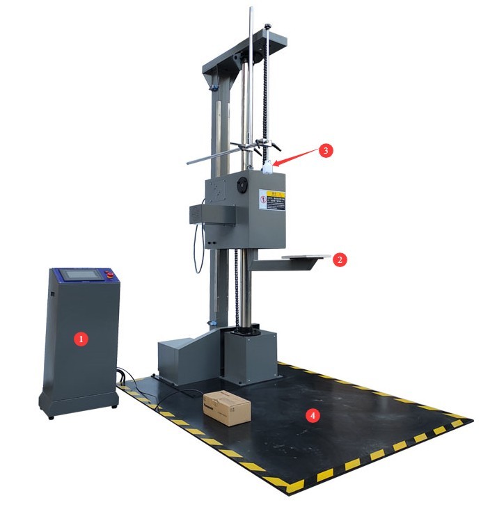
Figure 1
3.1.2 Dual-Arm Drop Tester
| No. | Note |
| ① | Control Cabinet |
| ② | Drop arms, both arms |
| ③ | Specimen Clamping Fixture |
| ④ | Base Plate |
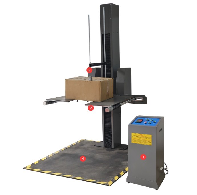
Figure 2
3.2 Introduction to the Control Cabinet
3.2.1 Single-Arm Drop Tester
| No. | Note |
| ① Altimeter | The top line displays the current altitude, and the bottom line displays the set drop altitude. |
| ② Settings button | Used to set the drop height |
| ③ Shift key | Change the digit when setting the drop height |
| ④ Value-Added Key | Adjust the size of the numbers when setting the drop height |
| ⑤ Reset Button | Minimum height for resetting the drop arm |
| ⑥ Drop Button | After pressing the button, perform a drop test. |
| ⑦ Up Arrow Key | When the button is pressed, the drop arm will rise to the set drop height. |
| ⑧ Down Arrow Key | When pressed, the drop arm will lower to its lowest position. |
| ⑨ Stop button | If you press the button while the drop arm is rising or lowering, it will stop rising or lowering. |
| ⑩ Reset Button | After the test is complete, press the reset button to return the drop arm to its original position and prepare for the next test. |
| ⑪ Power Button | Used to turn the power to the testing machine on or off |
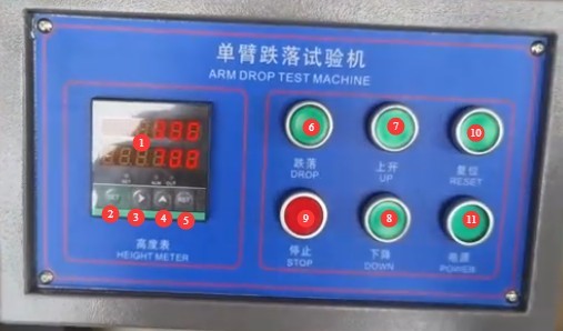
Figure 3
3.2.2 Dual-Arm Drop Tester
| No. | Note |
| ① Altimeter | The top line displays the current height; the bottom line displays the set drop height. |
| ② Settings Button | Used to set the drop height |
| ③ Shift key | Change the digit when setting the drop height |
| ④ Value-Added Key | Adjust the number value when setting the drop height |
| ⑤ Reset Button | Minimum height for resetting the drop arm |
| ⑥ Drop Button | After pressing the button, perform a drop test |
| ⑦ Up Arrow Key | When the button is pressed, the drop arm will rise to the preset drop height. |
| ⑧ Down Arrow Key | When pressed, the drop arm will lower to its lowest position. |
| ⑨ Stop button | If you press the button while the drop arm is rising or lowering, it will stop rising or lowering. |
| ⑩ Power Button | Used to turn the power to the testing machine on or off |
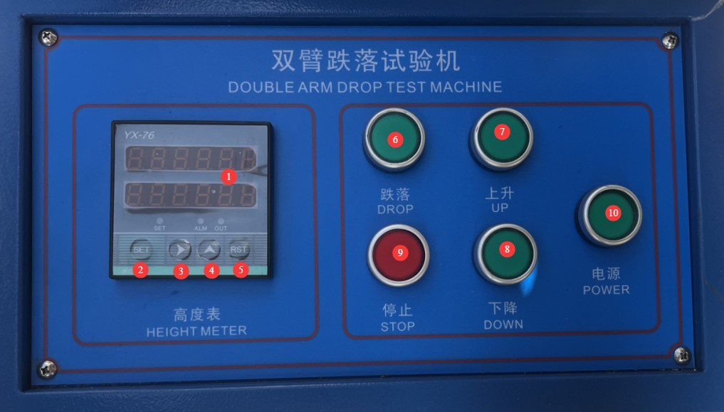
Figure 4
4. Preparations Before the Test
4.1 Sample Pretreatment
According to relevant standards, such as GB/T 4857.5-92/ISO 2248-1985, which apply to transport packaging, test specimens must be conditioned for 24 hours at a temperature of 23±2°C and a relative humidity of 50±5%.
4.2 Confirmation of Test Parameters
4.2.1 Drop Height
According to relevant standards, such as GB/T 4857.5-92/ISO 2248-1985, drop heights are determined based on the weight of the packaged item; the heavier the item, the lower the drop height. Common weight categories are as follows:
| Package Weight (kg) | Drop Height (mm) |
| <9.53 | 1000 |
| 9:53–18:59 | 760 |
| 18.59–27.67 | 650 |
| 27.67–45.36 | 500 |
| 45.36–68.04 | 400 |
| 68.04–90.72 | 300 (Note: Limited to single-arm testing machines; dual-arm testing machines require customization) |
| >90.72 | 200 (Note: A drop height of 200 mm requires customization) |
4.2.2 Drop Location and Number of Drops
In accordance with relevant standards, such as GB/T 4857.5-92/ISO 2248-1985.
| Project | Note |
| Core Posture | Free-fall drops onto one corner, three edges, and six faces, covering all possible impact surfaces |
| Angle Requirements | Maintain a stable posture during the fall to ensure that the designated part (corner/edge/face) makes contact with the impact surface first. |
| Typical Sequence | One corner (usually the most fragile 235 corner), three edges (the shortest, second-shortest, and longest edges adjacent to that corner), six faces (in the order 5→6→2→4→1→3) |
| Number of instances | Each specified orientation (corner/edge/face) must be dropped at least once; a complete test consists of 1 corner + 3 edges + 6 faces = 10 drops. The number of drops may be adjusted downward as agreed upon, but must not be less than 4. |
5. Drop Test Procedure
5.1 Resetting the Testing Machine
After powering on, press the reset button on the single-arm testing machine to return the drop arm to its original position; on the dual-arm testing machine, manually reset the test arms.
After the drop arm of the single-arm testing machine returns to its original position:
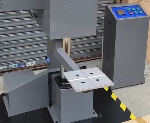
Figure 5
After the drop arms of the dual-arm testing machine return to their original positions:
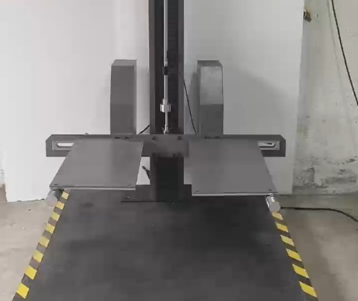
Figure 6
Press the “Down” button, and the drop arm will automatically lower to its lowest position. For single-arm drop testers, when the drop arm is at its lowest position, the height gauge should read 300 mm; for dual-arm drop testers, when the drop arms are at their lowest position, the height gauge should read 400 mm. If the reading is slightly off, press the reset button to restore the correct reading.
5.2 Setting the Drop Height
Press the Set button, then use the Shift and Increment buttons to set the drop height to the desired value. Once set, press the Set button again to return to standby mode.
5.3 Installing the Test Specimen
5.3.1 Single-Arm Drop Tester
Place the specimen in the exact center of the drop arm according to the test angle, edge, or face, and then secure it using the upper clamp.
5.3.2 Dual-Arm Drop Tester
The distance between the two arms can be adjusted according to the size of the specimen.
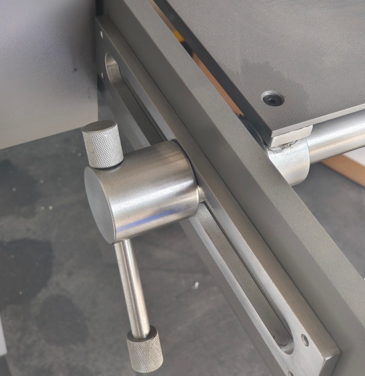
Figure 7
Place the specimen exactly in the center of the two drop arms according to the test angle, edge, or face, and then secure the specimen using the upper clamp.
5.4 Drop Test
Press the “Up” button, and the drop arm will automatically rise to the set drop height. Press the “Drop” button, and the drop tester will automatically perform the drop test.
During the drop, the operator observes the test specimen’s trajectory to confirm that it falls onto the impact panel at the specified location, without any deviation or collision with the fixture or drop arm.
After completing a single drop test, proceed to the next drop test as described in Section 5.1.
6. Post-Test Procedures
6.1 Shut Down and Clean the Equipment
Turn off the power to the equipment, clear all debris from the test area, and keep the area tidy.
Use a clean, soft cloth to wipe down the equipment control panel, digital display, fixtures, and impact panel to remove dust, debris, fingerprints, and other contaminants.
6.2 Evaluation of Test Results
According to the evaluation criteria specified in Clause 6.1.4 of the standard GB/T 4857.5-92/ISO 2248-1985, an individual item must meet all of the following requirements to be considered acceptable; failure to meet any one of these requirements results in the item being deemed unacceptable:
Packaging integrity: No damage that could compromise transport safety (such as cracked boxes, failed seals, or broken strapping); no significant deformation (such as collapsed edges or detached bases);
Condition of contents: No shifting, no damage, and no functional failure; for precision equipment (such as electrical lighting fixtures), the functional test requirements specified in the product standards must be met;
Effectiveness of the Protective Structure: The cushioning material shows no displacement or breakage, the inner packaging is secure, and it continues to provide protection.
6.3 Cleaning and Storage of Test Specimens
Gently transfer the tested specimens to the designated storage area, sort them according to their test status (passed/failed/pending inspection), and label them accordingly;
Remove dust and debris from the surface of the sample to prevent secondary contamination. If the sample is damaged, preserve the damaged portion for subsequent analysis.
7. Daily Maintenance and Care of Equipment
7.1 Daily Cleaning and Maintenance
Follow the instructions in Section 6.1 to clean the unit.
7.2 Lubrication and Maintenance
7.2.1 Identification of Lubrication Points
The key components of the equipment that require regular lubrication are: the sliding round rod (lifting rod), the pivot of the drop arm, the clamping mechanism adjustment screw, and all bearing joints.
7.2.2 Requirements for Lubricant Selection
Use only the low-concentration specialty lubricant supplied with the equipment, or a light-duty machine oil of equivalent specifications (viscosity grade ISO VG32);
Do not use: rust-preventive oil, highly concentrated motor oil, grease, hydraulic oil, or any corrosive oils, to prevent jamming of moving parts and motor overload.
7.2.3 Lubrication Intervals and Procedures
Routine Lubrication: Before each test, apply a thin film of lubricating oil to the surface of the sliding round rod. Use an amount sufficient to evenly cover the surface, but avoid applying too much;
Regular Lubrication: Apply lubricant once a week to the drop arm pivot shaft, the fixture adjustment lead screw, and the bearing areas. Apply 5–10 ml each time. After applying the lubricant, repeatedly adjust the fixture and rotate the drop arm to ensure the lubricant is evenly distributed;
Lubrication After Dust Removal: If there is excessive dust on the lubrication points, use a soft cloth to wipe away the old oil and dust, then refill with fresh lubricant.
7.3 Maintenance of Mechanical Components
7.3.1 Fastener Inspection and Tightening
Daily Inspection: Before the test, check that the mounting screws on the fixture and the impact panel are not loose;
Periodic Tightening: Since this is an impact-driven machine, perform the first comprehensive tightening after the new unit has been used a cumulative total of 500 times. Thereafter, tighten the fasteners once a month during routine use. Use an Allen wrench to tighten all fasteners on the equipment (motor, lifting unit, drop arm, and main frame) one by one to prevent screws from loosening due to impact;
Tighten with moderate force to prevent the screw from stripping or breaking.
7.3.2 Maintenance of Moving Parts
Drop Arm: Periodically check that the spring buffer returns to its normal position and is free of deformation or breakage. If the return force is weak, contact customer service immediately to have it replaced;
Flagpole: Check that the surface is free of scratches and rust. If there is minor rust, sand it down with fine-grit sandpaper and then apply lubricating oil;
Fixtures: Periodically check that the clamping force of the fixtures is normal and that the lead screws move smoothly without deformation or binding. If a lead screw becomes stuck, clean it and apply lubricant.
7.4 Long-Term Storage
If the device will not be used for an extended period, store it in a dry, well-ventilated area, away from moisture and direct sunlight;
Disconnect all cables, store the accessories separately, and cover the device with a dust-proof cloth;
Turn on the device and let it run for 30 minutes each month to prevent the internal electronic components from deteriorating and to verify that the device is functioning properly.
8. Troubleshooting and Resolving Common Problems
8.1 Electrical Faults
8.1.1 Power Failure
| Fault Symptoms | Possible Causes | Procedure |
| The device won’t turn on | 1. The power supply circuit breaker is not closed; 2. The power cord connections are loose or broken; 3. The power supply voltage is incorrect; 4. The device’s power switch is damaged | 1. Check and close the circuit breaker; 2. Check the power cord connections, and either plug it back in securely or replace the power cord; 3. Verify that the power supply is 380V, 50/60 Hz, and that the voltage is normal; 4. If the power switch is damaged, contact customer service to have it replaced. |
8.1.2 Instrument Malfunctions
| Fault Symptoms | Possible Causes | Procedure |
| The digital display is blank, and the buttons are unresponsive. | 1. The device is not powered on; 2. The digital display has loose wiring; 3. The digital display is damaged | 1. Check that the power supply is connected properly; 2. Contact customer service to inspect the wiring and retighten any loose connections; 3. If the digital display is damaged, contact customer service to have it replaced. |
| The digital display is distorted, and the values are fluctuating erratically. | 1. Loose encoder wiring; 2. Damaged encoder; 3. Internal instrument malfunction | 1. Turn off the power and contact customer service to have the encoder wiring checked; 2. If the encoder is damaged, contact customer service to have it replaced; 3. If the instrument is malfunctioning, contact customer service for calibration or repair. |
8.1.3 Motor Malfunctions
| Fault Symptoms | Possible Causes | Procedure |
| The drop arm cannot be raised or lowered; the motor is not responding. | 1. Loose motor wiring; 2. Motor overload protection triggered; 3. Motor damage | 1. Contact customer service to have the motor wiring inspected; 2. Turn off the power, let the unit cool for 10 minutes, then restart it to avoid overloading; 3. If the motor is damaged, contact customer service for repair or replacement. |
| The motor makes unusual noises and overheats during operation. | 1. The motor bearings are low on oil; 2. Dust has entered the motor; 3. The lifting mechanism is jammed, causing the motor to overload | 1. Contact customer service to have lubricant applied to the motor bearings; 2. Use compressed air to blow out dust from inside the motor; 3. Troubleshoot the cause of the jamming in the lifting mechanism, and resume operation after resolving the issue. |
8.2 Mechanical Failures
8.2.1 Drop Arm Malfunction
| Fault Symptoms | Possible Causes | Procedure |
| After pressing the drop button, the drop arm does not release the specimen. | 1. The clamping force of the fixture is too high; 2. The drop arm release mechanism is jammed; 3. The release solenoid valve is malfunctioning | 1. Slightly loosen the clamping force of the fixture; 2. Clean dust from the release mechanism and apply lubricant; 3. Contact after-sales service for solenoid valve malfunctions. |
| Abnormal rebound of the drop arm; poor cushioning performance | 1. Deformation or breakage of the spring buffer; 2. Lack of oil in the buffer | 1. Contact customer service to have the spring buffer replaced; 2. Apply special lubricant to the buffer. |
8.2.2 Fixture Malfunctions
| Fault Symptoms | Possible Causes | Procedure |
| The fixture was not clamped securely, and the specimen came loose before it fell. | 1. Insufficient clamping force of the fixture; 2. Oil residue on the fixture’s contact surface; 3. Deformation of the fixture | 1. Increase the clamping force of the fixture; 2. Clean oil and grease from the fixture’s contact surfaces and keep them dry; 3. If the fixture is deformed, contact customer service for adjustment or replacement. |
8.3 Drop Height Error Exceeds Specifications
| Fault Symptoms | Possible Causes | Procedure |
| The deviation between the height displayed on the digital display and the actual height is greater than ±10 mm. | 1. Encoder misalignment/damage; 2. Instrument parameters have been altered; 3. The drop arm is not moving vertically | 1. Contact customer service to calibrate or replace the encoder; 2. Contact customer service to restore the instrument to its factory settings and recalibrate it; 3. Check that the lifting arm is not deformed and adjust the vertical alignment of the drop arm. |