
 English
 中文简体
中文简体 English
 Русский
 Español
 Português
 Türkçe
 العربية
 Deutsch
 Polski
 Italiano
 Français
 한국어
한국어 ไทย
ไทย Tiếng Việt
 日本語
日本語





























Digital CC And CV DC Power Supply
User's Manual
Applicable LISUN models: DC100020B、DC12010B、DC12030B、DC3050B、DC50010B
1. Unboxing and Basic Familiarization with the Equipment
1.1 Key Technical Specifications
| Specifications/Model Numbers | DC3050B | DC12030B | DC50010B |
| Maximum Output Voltage and Current | 30 V/50 A | 120 V/30 A | 500 V/10 A |
| Voltage Resolution | 0.01 V (<100 V); 0.1 V (>100 V) | ||
| Voltage Accuracy | ±0.1 V | ||
| Current Resolution | 0.01 A (<100 A); 0.1 A (>100 A) | ||
| Current Accuracy | ±0.1 A | ||
1.2 Unboxing Inspection and Verification of Accessories
1.2.1 Unpacking and Visual Inspection
When unpacking the device, handle it gently to avoid scratching the outer casing with sharp tools. After unpacking, first inspect the exterior of the device to ensure there is no visible deformation or dents, and that the buttons are not damaged or loose. If you notice any abnormalities with the device or its accessories, do not turn it on. Please contact us immediately.
1.2.2 Main Unit and Accessories
Host: 1 DC-B Series power supply, with the input power supply cord pre-installed.
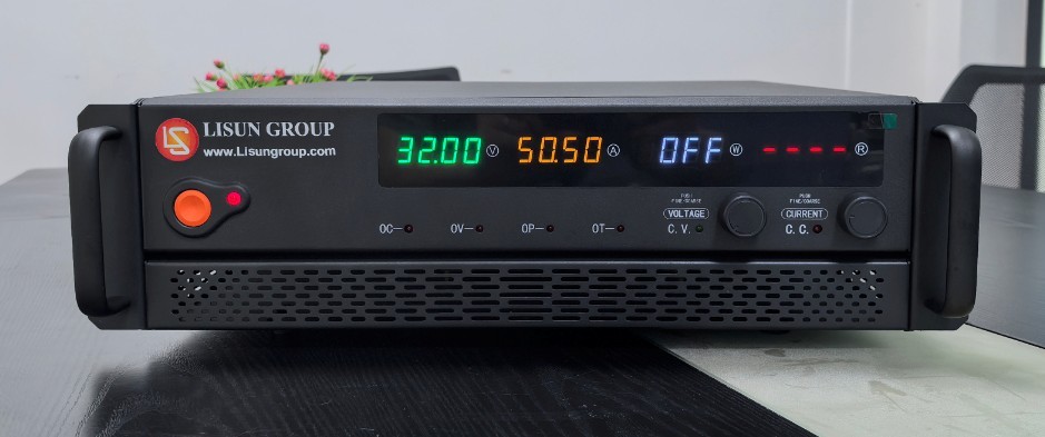
Figure 1
Other accessories are as follows:
| Number | Note |
| ① | Equipment Handle Mounting Accessories |
| ② | USB Cable |
| ③ | RS-232 Cable |
| ④ | Sampling Line Accessories |
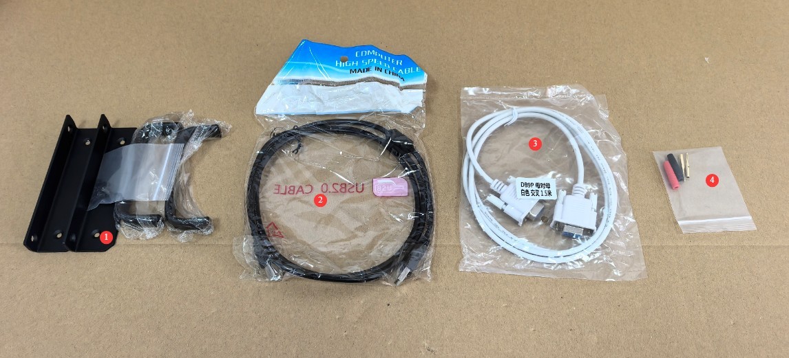
Figure 2
Note: The standard DC-B unit does not include PC software and does not require a USB or RS-232 cable. If you need to use PC software to control the DC power output, please contact us for a custom solution.
Links to download the electronic user manual, warranty card, and other documents have been sent via email. Please download them as soon as possible. If you missed the email, please feel free to contact us to receive the download links again.
2. Safety Precautions
2.1 Electrical Safety Standards
The equipment requires a single-phase AC 220 V ±10 V input power supply that complies with safety standards and is equipped with a proper protective grounding system to prevent electric shock.
2.2 Environmental Safety Standards
For indoor use only; avoid direct sunlight. Place on a sturdy, stable surface to avoid severe vibrations. Keep away from dust, corrosive gases, and flammable or explosive materials. Keep away from strong magnetic and electric fields. Ensure good ventilation; leave at least 10 cm of space around the device for heat dissipation, and do not block the cooling fan vents. Operating Environment: Temperature 5°C to 35°C, relative humidity <65% RH.
2.3 Operational Safety Guidelines
Do not operate the equipment or plug in/unplug the power cord with wet hands; the output must be turned off before connecting or disconnecting wires; allow the unit to warm up for at least 10 minutes after powering on before enabling the output; Do not touch the output terminals, internal components, the load, or the load wiring while the equipment is operating; allow at least 3 minutes between powering on and off to prevent damage from electrical surges; do not shut down the equipment directly while it is in output mode; first shut off the output before powering down; if you notice an unusual odor, smoke, unusual noise, or overheating, immediately disconnect the power and do not continue operation.
3. Equipment Overview and Wiring
3.1 Introduction to the Front Panel
| Number | Note |
| ① | Power Switch |
| ② | Output Switch |
| ③ | Voltage Display Window V |
| ④ | Current Display Window A |
| ⑤ | Power display window W; displays “OFF” when no power is being output |
| ⑥ | Equivalent impedance display window R; displays “—-” when no output is present. |
| ⑦ | Overcurrent Protection |
| ⑧ | Overvoltage Protection |
| ⑨ | Over-Power Protection |
| ⑩ | Over-Temperature Protection |
| ⑪ | Constant Voltage (CV) Output Indicator Light |
| ⑫ | Pressure Control Knob |
| ⑬ | Constant Current (CC) Output Indicator Light |
| ⑭ | Flow Control Knob |
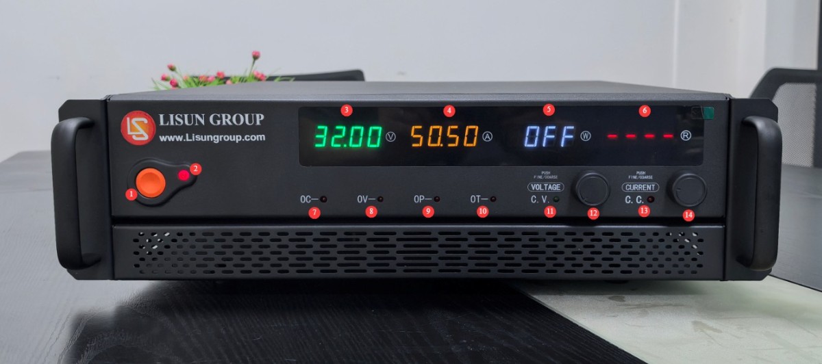
Figure 3
3.2 About the Back Panel
3.2.1 Regarding the Input Power Supply Cord
Depending on the power rating of the equipment, the pre-installed power cord will vary.
| Number | Note |
| ① | Low-power devices come pre-installed with standard mains power plugs |
| ② | High-wattage appliances come pre-installed with thicker power cords; do not plug them directly into low-wattage outlets. |
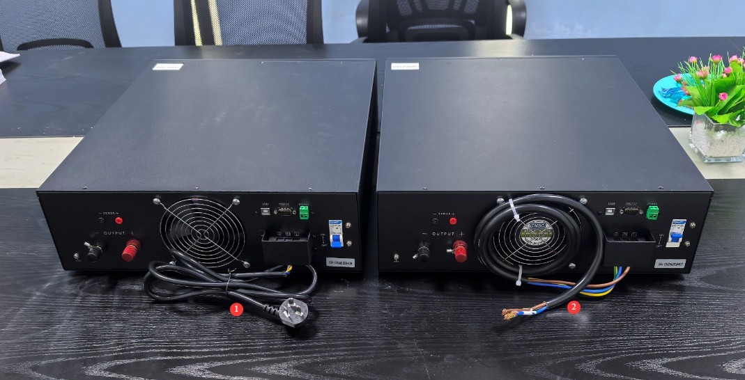
Figure 4
3.2.2 Introduction to the Back Panel and Wiring
| Number | Note |
| ① Power cord | Connect the device to an appropriate power source |
| ② Power Circuit Breaker | |
| ③ Output Terminals | Connect to your DC load |
| ④ Sampling Terminal | It also connects to your DC load, allowing you to obtain a more accurate load-side voltage. If you require high voltage sampling accuracy, please connect it; leaving it unconnected does not affect the DC power supply’s output functionality. |
| ⑤ Ground Terminal | If your load requires a ground connection, you can connect its ground wire to this terminal. |
| ⑥ Communication Port | If you need the device to communicate with a computer, connect a USB/RS232/RS485 cable to the computer. |
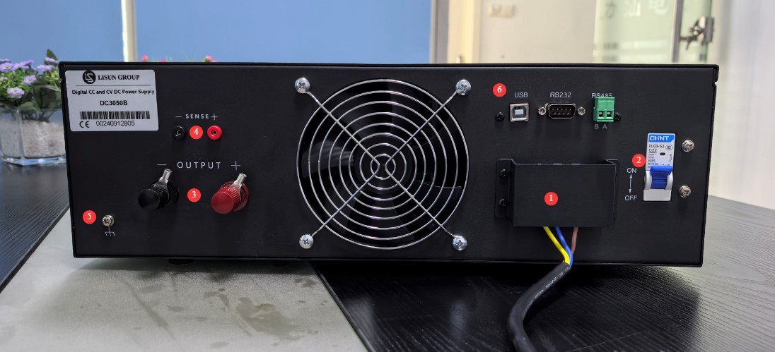
Figure 5
Note: If the sampling terminals are connected, this is a 4-wire sampling configuration, which eliminates cable voltage drop; if the sampling terminals are not connected, cable voltage drop is included.
4. Equipment Operation
4.1 Constant-Voltage Output
4.1.1 Current Adjustment
If constant-voltage output is required, the current serves as a current-limiting reference. You can set it directly to the maximum value, or at least to a value sufficient to maintain the set constant voltage. If the current is set too low, the current limit will be triggered, and constant-voltage output cannot be maintained.
| Instructions | Note |
| ① | Press the current adjustment knob, and the last digit in the current display window will begin to flash. |
| ② | Turn the flow control knob to change the digit in that position. |
| ③ | Continue pressing the flow adjustment knob to cycle through the other digits, and use the same method to change each digit. |
| ④ | After completing the setup, wait 2 seconds; the device will automatically exit setup mode. |
4.1.2 Adjusting the Voltage
If a constant-voltage output is required, set the voltage to the load’s rated voltage.
| Instructions | Note |
| ① | Press the voltage adjustment knob, and the last digit of the voltage display will begin to flash. |
| ② | Turn the volume control knob to change this digit. |
| ③ | Continue pressing the voltage adjustment knob to cycle through the other digits, and use the same method to change that digit. |
| ④ | After completing the setup, wait 2 seconds; the device will automatically exit setup mode. |
4.1.3 Turn Output On/Off
Example: I need a constant-voltage output of 22V. Set it up as follows.
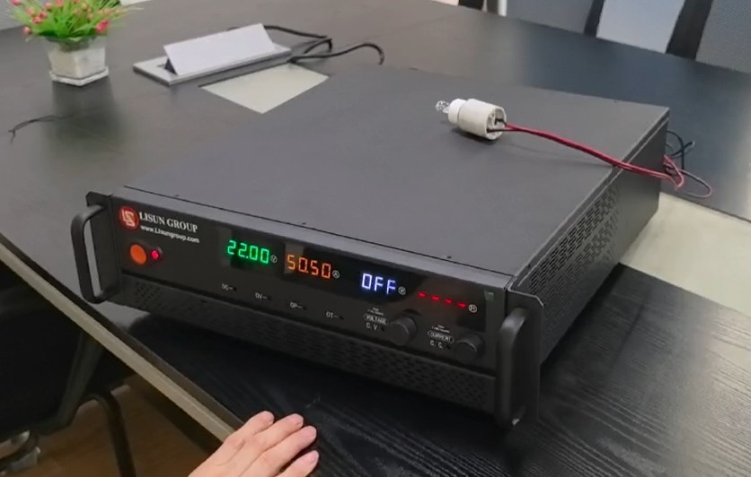
Figure 6
| Number | Note |
| ① | Press the output switch to activate the output. |
| ② | The constant-voltage indicator light is on, and the device is in constant-voltage output mode. |
| ③ | The voltage display window shows the output voltage, which matches the set value. |
| ④ | The current display window shows the output current. It does not need to match the set value, but the set value must be higher than the actual value; otherwise, constant-voltage output will not be possible. |
| ⑤ | The power display window shows the output power. |
| ⑥ | The Equivalent Impedance window displays the equivalent impedance of the current output line. |
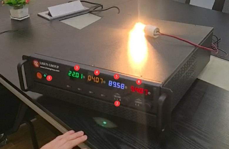
Figure 7
Press the output switch again to turn off the output.
4.2 Constant-Current Output
4.2.1 Adjusting the Voltage
If constant-current output is required, the voltage serves as the over-voltage limit reference. You can set it directly to the maximum value, or at least to a value that satisfies the set constant-current value. If the voltage is set too low, it will trigger the over-voltage limit, and the constant-current output cannot be maintained.
For instructions on adjusting the voltage, see Section 4.1.2.
4.2.2 Current Adjustment
If a constant current output is required, set the current value to the load’s rated current.
For instructions on adjusting the current, see Section 4.1.1.
4.2.3 Turning the Output On/Off
Example: I need a constant current output of 4.00 A. Set it up as follows.
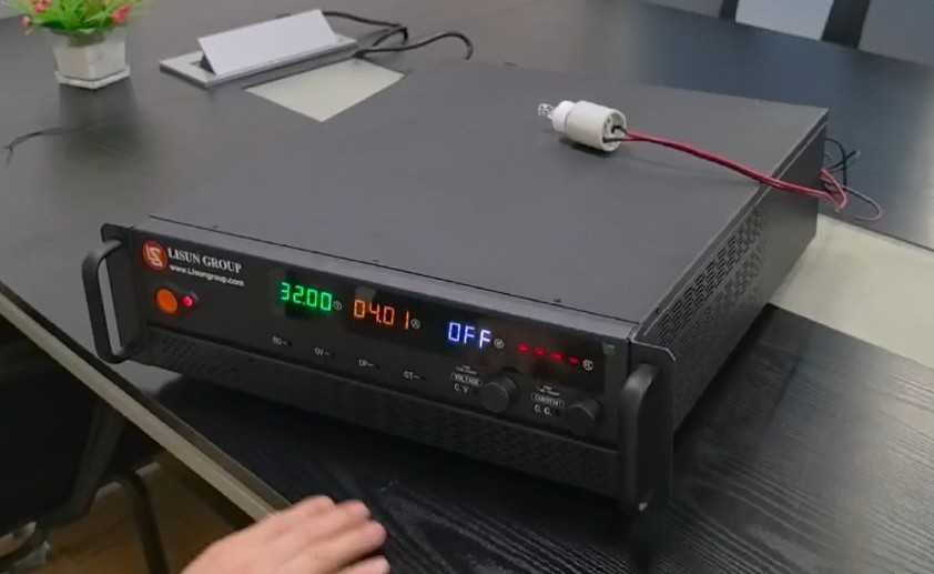
Figure 8
| Number | Note |
| ① | Press the output switch to activate the output. |
| ② | The constant-current indicator is lit, and the device is in constant-current output mode. |
| ③ | The voltage display window shows the output voltage, which does not need to match the set value; however, the set value must be higher than the actual value, otherwise constant-current output will not be possible. |
| ④ | The current display window shows the output current, which matches the set value. |
| ⑤ | The power display window shows the output power. |
| ⑥ | The Equivalent Impedance window displays the equivalent impedance of the current output line. |
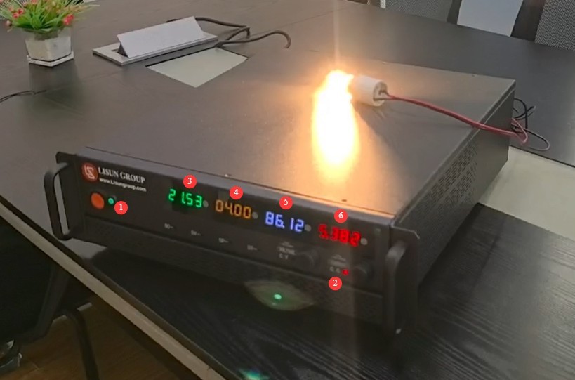
Figure 9
Press the output switch again to turn off the output.
5. Daily Maintenance and Care of Equipment
5.1 Routine Maintenance
5.1.1 Daily Cleaning
Be sure to turn off the power and unplug the power cord before cleaning. We recommend wiping the device with a soft, anti-static cotton cloth and a mild detergent; do not spray liquids directly onto the device. Do not use chemical solvents such as benzene, toluene, or acetone.
5.1.2 Routine Inspections
Before each use, check that the power cord and terminal connections are secure and free of burn marks; ensure that the fan vents are not blocked; and after turning on the unit, verify that the indicator lights and display are functioning properly.
5.2 Storage Specifications
5.2.1 Storage Environment Requirements
Temperature: 5°C to 35°C; relative humidity: <65% RH; dry, dust-free environment free of corrosive gases.
5.2.2 Long-Term Storage Operations
Turn off the power and unplug all cables; clean the equipment and wrap it in dust-proof film; turn on the power for 10 minutes each month to prevent moisture damage to the components.
Troubleshooting and Resolving Common Issues
6.1 Equipment Alarm Indicator Lights
| Fault Symptoms | Possible Causes | Procedure |
| The OV indicator light is on | Overvoltage Protection | Turn off the output, check that the voltage setting does not exceed the device’s maximum output voltage, and then turn the output back on. |
| The OC indicator light is on | Overcurrent Protection, Load Short Circuit | Turn off the output; check that the current setting does not exceed the device’s maximum output current; check the load, rule out a short circuit, and then resume output. |
| The OP indicator light is on | Over-Power Protection | Turn off the output, reduce the voltage/current, and lower the load power, then resume output |
| The OT indicator light is on | Over-Temperature Protection | Turn off the output, let the device cool down by disconnecting the power, clean the fan vents to improve heat dissipation, and then restart the device once it has cooled down and try again. |
6.2 Other Malfunctions
| Fault Symptoms | Possible Causes | Procedure |
| Unable to Power On | Loose input power supply cord, blown fuse | Turn off the power and check the input power supply cord connection; turn off the power, troubleshoot for short circuits or overloads, replace the fuse with one of the same rating, and do not use a fuse with a higher current rating. |
| Output parameters are incorrect | Incorrect voltage and current settings | Please refer to Chapter 4 to set the parameters correctly. |
| The fan isn’t spinning | Dust buildup, motor failure | Turn off the power and clean the dust from the fan. If the problem persists, please contact us for repair or to have the fan replaced. |