
 English
 中文简体
中文简体 English
 Русский
 Español
 Português
 Türkçe
 العربية
 Deutsch
 Polski
 Italiano
 Français
 한국어
한국어 ไทย
ไทย Tiếng Việt
 日本語
日本語





























Multiway Life Tester
User's Manual
Applicable LISUN models: CH316
1. Unboxing and Basic Familiarization with the Device
1.1 Key Technical Specifications
| Parameters | Note |
| Test Channel | Supports simultaneous testing of 16-channel products, with independent evaluation and separate recording of switch life for each channel |
| Service Life Range | 0 to 1000,000 times |
| Time Settings | The power-on and power-off times can be set arbitrarily within a range of 1 second to 99 hours, 59 minutes, and 59 seconds. |
| Load Current | 30 mA to 1000 mA (RMS); monitoring is not possible if the load current is less than 30 mA |
| Alarm Function | When a circuit reaches the end of its service life, the instrument will emit six consecutive beeps, and the corresponding indicator light will illuminate. |
| Unexpected Power Outage | Automatically saves test results and resumes the previous test when power is restored |
1.2 Unboxing and Checking the Contents
1.2.1 Unpacking and Visual Inspection
When unpacking the device, handle it gently and avoid using sharp tools that could scratch the exterior casing. After unpacking, first inspect the exterior of the device to ensure there is no visible deformation or dents, and that the buttons are not damaged or loose. If you notice any abnormalities with the device or its accessories, do not turn it on. Please contact us immediately.
1.2.2 Main Unit and Accessories
| Number | Note |
| ① | CH316 Multiway Life Tester Main Unit |
| ② | Power Cord |
Download links for the digital user manual, software, warranty card, and other materials have been sent via email. Please download them as soon as possible. If you missed the email, please feel free to contact us to request the download links again.
2. Safety Precautions
2.1 General Safety Standards
2.1.1 Environmental Requirements
The instrument should be used in a laboratory environment at room temperature that is dry and well-ventilated, and should be kept away from moisture, dust, and corrosive gases;
Do not operate the instrument in explosive atmospheres or near flammable or explosive materials to prevent electrical sparks from causing a hazard;
The instrument should be placed on a stable surface, at a distance of at least 50 cm from heat sources (such as ovens or electric furnaces), and the display window should be protected from direct sunlight;
Avoid severe vibrations to prevent loose connections or internal components from becoming loose.
2.1.2 Personnel Operating Requirements
Operators must have a basic understanding of electrical systems, familiarize themselves with this manual before operation, and must not operate the equipment in violation of the instructions;
Wear an antistatic wrist strap during operation to prevent static electricity from damaging the microcomputer components inside the instrument;
While the equipment is in operation, do not touch the wiring ports or terminal blocks with your hands to prevent electric shock.
2.2 Electrical Safety Requirements
2.2.1 Power Supply Requirements
The instrument may only be connected to a 220 V AC ±10%, 50/60 Hz mains power supply;
Avoid sharing the same power circuit with high-power equipment (such as welders and air compressors) to prevent voltage fluctuations from affecting the equipment’s operation.
2.2.2 Grounding Safety Standards
The instrument must be reliably grounded, with the grounding terminal connected to the laboratory’s dedicated grounding electrode; the grounding resistance must be ≤4 Ω;
The ground wire in the power supply system must be connected separately; it must not be shared with the neutral wire to prevent equipment malfunctions caused by a live ground wire;
Before turning on the power, be sure to check that the ground connection is secure; never turn on the instrument if it is not grounded.
2.3 Safety Precautions During Operation
2.3.1 Operations Strictly Prohibited While the System Is Energized
Do not connect or disconnect wires while the power is on: All load wiring and sample replacement operations must be performed after the load power has been turned off;
Never replace a fuse while the power is on: To replace a fuse, first turn off the power, unplug the power cord, and then open the fuse compartment on the unit;
Do not touch internal components while the power is on: There is high voltage inside the instrument; non-professionals must not open the case while the power is on.
2.3.2 Equipment Operation Contraindications
Do not remove the instrument casing or disconnect the wiring ports without authorization; removal without the manufacturer’s permission will void the warranty;
Do not press the buttons or scratch the display window with sharp objects to avoid damaging the button contacts and the display film;
Do not place heavy objects or liquids on the instrument to prevent deformation of the housing and damage to internal circuits caused by liquid leakage;
Use the “Clear All” function with caution. Be sure to verify that all test data has been recorded before proceeding to avoid data loss.
3. Preparations Before the Test
3.1 Preparation of Test Samples
Verify the rated current of the test sample to ensure its RMS value falls within the range of 30 mA to 1000 mA, to prevent the instrument from being unable to make a determination due to an excessively low current; confirm that the sample does not have any abnormal protection circuits (the instrument may not be suitable for loads with abnormal protection circuits);
Verify that all samples are AC-powered and that the required input power supply voltage is the same.
3.2 Equipment Overview and Wiring
3.2.1 Introduction to the Equipment Back Panel and Wiring
| Number | Note |
| ① | 16-channel load terminal block; can be configured for any single or multiple channels as needed |
| ② | Connect the device’s power cord to a 220 V AC ±10%, 50/60 Hz mains power source. |
| ③ | Power Input Fuse |
| ④ | Load Power Supply Terminals: A suitable power source must be provided separately for the load and connected. |
| ⑤ | Load circuit fuse: The total load current must not exceed 8 A. |
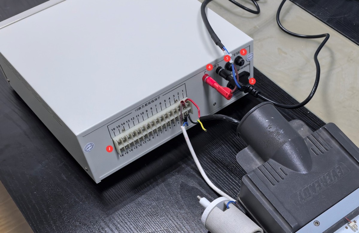
Figure 1
3.2.2 Power-On and Front Panel Display
Once you have verified that all connections are secure, you may turn on the power. After power-up, the CH316 will automatically perform a switch life test according to the preset parameters. If you do not wish to use the default parameters for the test, press the Pause button, reconfigure the parameters, and then press the Pause button again to resume the test.
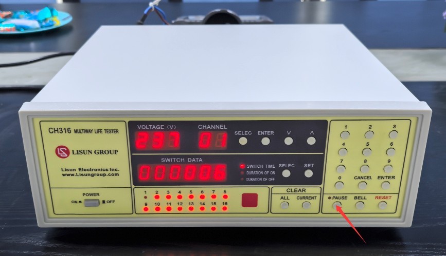
Figure 2
Introduction to the CH316 Front Panel Display.
| Project | Note | |
| ① | Display the load supply voltage | |
| ② | Display the current channel number | |
| Adjust the display channel number | Method 1 | ③ Press the Select button |
| ④ Use the number keys to enter the channel you want to view, such as 04, 15, etc. | ||
| ⑤ Just press “Confirm” | ||
| Method 2 | ⑥ Use the up and down arrow keys to switch channel numbers directly | |
| ⑦ | Displays the number of switch cycles or the time the current channel has been powered on (or off) | |
| ⑧ | Press the right selection button to toggle between the number of switching cycles and the power-on time (or power-off time). | |
| ⑨ | In the alarm window, red lights will illuminate for lanes with no samples or where samples are damaged; the life cycle testing for these lanes has been automatically stopped. | |
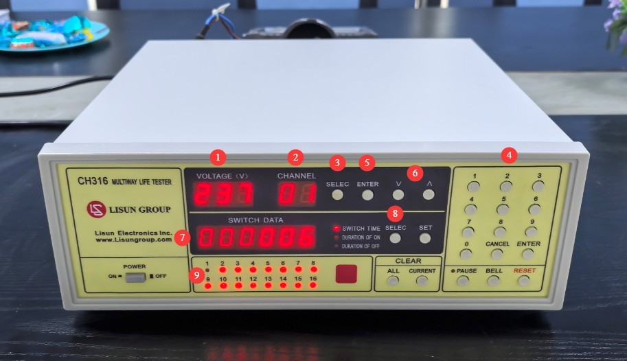
Figure 3
Life Test Procedures
4.1 Power-On/Power-Off Timer Settings
| Number | Note |
| ① | Press the Settings button |
| ② | The power indicator light turns on |
| ③ | The first digit in the display window flashes; the time is displayed in the hour-minute-second format, with a total of 6 digits. |
| ④ | Use the numeric keys to enter the desired power-on time sequentially, padding with zeros for any missing digits (e.g., for 0 hours, 02 minutes, and 15 seconds, enter 000215). |
| ⑤ | If you made a mistake or don’t need to make any settings, simply press the “Cancel” button. |
| ⑥ | After entering the correct value, press the Confirm button; the power-off indicator will light up, and the first digit in the display window will flash. Use the same method to complete the power-off time setting. |
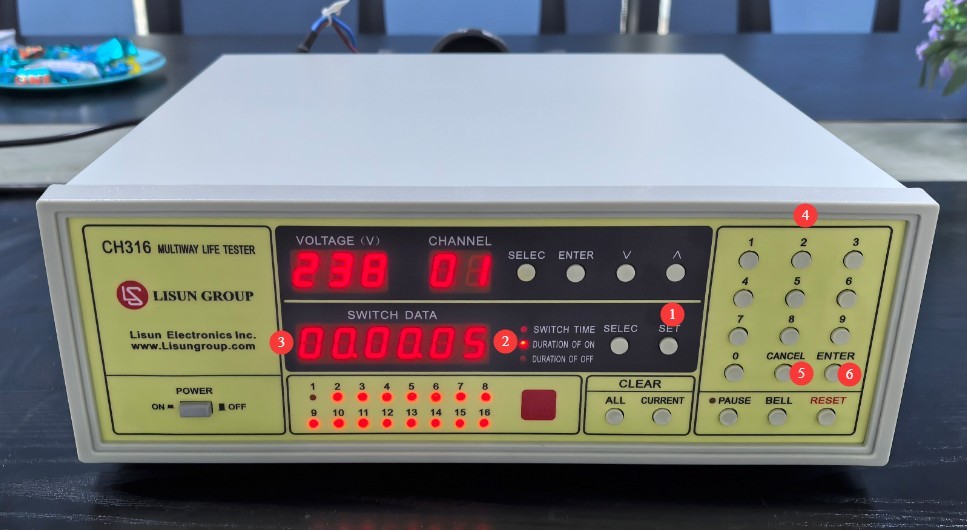
Figure 4
Once the settings are successfully configured, the device will automatically continue the switch life test according to the newly set power-on and power-off times.
4.2 Resetting Test Data
4.2.1 Clearing Data on a Single Channel
Key Scenario: When replacing a new sample on a specific channel, clear the existing count data for that channel to prevent accumulation.
| Number | Note |
| ① | Press the single-channel button |
| ② | The Switch Parameters window displays “CLRONE” |
| ③ | The first digit on the channel display is flashing. |
| ④ | Use the number keys to enter the channel numbers you want to reset, such as 08, 12, etc. |
| ⑤ | If you made a mistake or don’t need to reset, simply press the “Cancel” button. |
| ⑥ | After verifying that the channel number is correct, press the Confirm button. The data for that channel will be cleared, and the instrument will automatically exit the clear mode. |
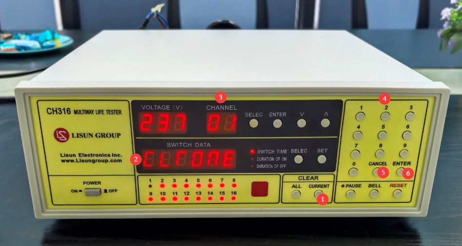
Figure 5
Once the reset is complete, the number of times the channel has been toggled will be reset to 0, and the original data cannot be recovered.
4.2.2 Reset All Data to Zero
Key Scenario: If all 16 channels are replaced with new samples, the test for all channels may need to be restarted. Use with caution!
Press the “All” button; the parameter window will display “CLR ALL,” indicating that the system has entered the “Clear All” confirmation mode;
If you made a mistake or don’t need to reset, simply press the Cancel button;
After confirming that all channels need to be reset, press the confirmation key three times in a row to reset all 16 channels; the instrument will automatically exit the reset mode;
Once the reset is complete, the count for all route switches will be reset to 0, and the original data cannot be recovered.
4.3 Checking, Replacing, or Adding Samples During Testing
| Project | Instructions | ||
| 1 | 2 | 3 | |
| Unexpected alarm in a certain passageway | Press the pause button, stop the instrument test, and turn off the load power supply. | Check the sample wiring | Turn on the sample load power supply, press the Pause button again, and resume the test. |
| Sample Damage Alert | Record the number of times the sample is switched on and off, replace the sample, and ensure the wiring is correct. | Turn on the sample load power supply, perform a single-channel data reset for that channel, press the Pause button again, and resume the test. | |
| Need to add a sample | Add the sample and make sure the wiring is correct. | ||
4.4 End of Testing
Before turning off the power to the instrument, press the “View” button and enter channel numbers 1 through 16 in sequence to view and record the final number of on/off cycles for each channel;
For each alarm channel, record separately the number of times the switch was activated when the alarm was triggered, as well as the cause of the alarm (sample damage/wiring issue);
Then turn off the power to the instrument and the load.
5. Daily Maintenance and Care of Equipment
5.1 Daily Cleaning and Maintenance
Cleaning the Instrument Surface: Wipe the exterior of the instrument with a dry, soft, lint-free cloth to remove dust and stains. Do not use wet cloths, alcohol, detergents, or other corrosive liquids for cleaning;
Cleaning the terminal block: Gently clean the gaps with a soft-bristled brush to prevent dust and debris from accumulating and causing poor contact;
Cleaning the Display Window: Dip a lint-free cloth in a small amount of distilled water and gently wipe the display window to remove fingerprints and smudges. After wiping, dry it with a dry cloth to prevent water marks from forming.
5.2 Long-Term Storage
If the device will not be used for an extended period, store it in a dry, well-ventilated area, away from moisture and direct sunlight;
Disconnect all cables, store the accessories separately, and cover the device with a dust-proof cloth;
Turn on the device for 30 minutes each month to prevent the internal electronic components from deteriorating.
6. Troubleshooting and Resolving Common Problems
| Fault Symptoms | Possible Causes | Procedure |
| No display and no response upon startup | Input Fuse Blown | Open the fuse compartment, check if the fuse has blown, and replace it with a fuse of the same rating. |
| Instrument Freeze | Interference in the input power supply or the environment | Press the power button to perform a cold boot, or press the RESET button to perform a warm boot. |
| None of the samples could be started. | Load Power Supply Fuse Blown | Open the fuse compartment, check if the fuse has blown, and replace it with a fuse of the same rating. Also, ensure that the total load current does not exceed 8A. |
| The sample can be started, but the channel is still triggering an alarm. | The load current may be less than 30 mA | If the load current is less than 30 mA, the instrument cannot perform effective monitoring. Please replace the test sample with one that has a rated current of ≥30 mA. |
| The sample is not subjected to on/off operations. | Incorrect power-on/power-off parameter settings | Refer to Section 4.1 to reconfigure the settings. |
| An alarm went off in a certain lane for no apparent reason | The sample has an abnormal protection circuit. | This instrument may not be suitable for loads equipped with abnormal protection circuits; please replace or adjust the sample. |