
 English
 中文简体
中文简体 English
 Русский
 Español
 Português
 Türkçe
 العربية
 Deutsch
 Polski
 Italiano
 Français
 한국어
한국어 ไทย
ไทย Tiếng Việt
 日本語
日本語





























Coupling Decoupling Network
User's Manual
Applicable LISUN models: CDNE-M216、CDNE-M316
1. Overview
The CDNE is designed in accordance with the requirements for CDNE networks specified in CISPR15-2018, CISPR 16-1-2 (2017), and GB 6113.102-2018 regarding CDNE network requirements. When used in conjunction with LISUN’s EMI-9KB, it is a network specifically designed for measuring disturbance voltages in the 30 MHz–300 MHz frequency range.
Divided into second-tier and third-tier:
The CDNE-M216 (two-wire) is suitable for test subjects with two power wires (i.e., the live wire and the neutral wire).
The CDNE-M316 (3-wire) is suitable for test objects with a 3-wire power cord (i.e., live wire, neutral wire, and ground wire).
According to the latest CISPR 15 (2018) standard, a CDNE network is used in place of a CDN network to measure radiated disturbance from electrical lighting equipment in the 30–300 MHz range. The use of a CDNE or CDN network to measure radiated disturbance is referred to as an independent method for radiated disturbance measurement.
This independent measurement method significantly reduces the financial burden on users, since conducting measurements using an antenna, a 10-meter measurement distance, and a half-wave anechoic chamber requires equipment that only a very small number of well-resourced organizations can afford to set up.
Among independent methods for measuring radiated emissions, using a CDNE network is preferable to using a CDN network. The frequency range of a CDN network is typically 0.15–80 MHz, while that of a CDNE network is 30–300 MHz.
2. Basic Principles
The CDNE Coupling and Decoupling Network consists of two parts: coupling and decoupling. The primary function of decoupling is to prevent useful signals from leaking into the power supply side (AE port) while also preventing interference from the power supply side from affecting the useful signals. The function of coupling is to transmit interference signals from the equipment under test (EUT port) to the signal port (RF port) for measurement by the test instrument.
See Figures 1 and 2 for the circuit diagrams of the CDNE Coupling and Decoupling Network.
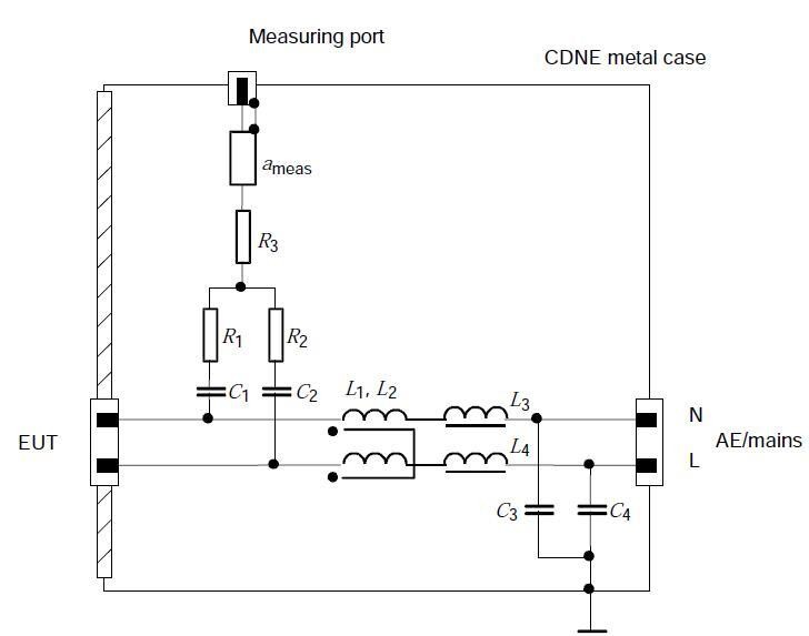
Figure 1 CDNE-M216 Circuit Block Diagram
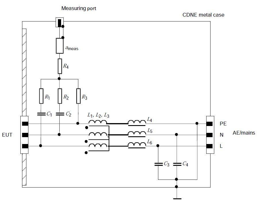
Figure 2 CDNE-M316 Circuit Block Diagram
AE/mains: The external power input port of the CDNE network; this power is transmitted through the CDNE network and delivered to the EUT.
EUT: The power output terminal of the CDNE network; connect the power cord of the device under test here.
Measurement port: CDNE network signal port; connects to the measurement receiver
3. Performance and Technical Specifications
CDNE Coupling/decoupling networks are used for radiated disturbance measurements in electrical lighting equipment within the 30–300 MHz range, meeting the requirements for this instrument specified in standards CISPR 16-1-2 (2017) and GB 6113.102-2018. Its main performance and technical specifications are as follows:
| No. | Parameters | Indicators |
| 1 | Measurement Frequency Range | 30–300 MHz |
| 2 | AE Supply Voltage Range | AC: Line-to-line 0–520 V, Line-to-ground 0–300 V; DC: 0–300 V |
| 3 | Current Range | 0–16 A |
| 4 | Asymmetric (Common-Mode) Impedance of the EUT Port | 150 Ω +10 –20 Ω Phase angle: 0° ± 25° |
| 5 | Symmetrical (differential-mode) impedance at the EUT port | 100 Ω ± 20 Ω |
| 6 | Longitudinal Conversion Loss (LCL) | ≥20 dB |
| 7 | Decoupling Attenuation | >30 dB |
| 8 | Standard Signal Coupling Attenuation Value (Including a 10 dB Built-in Attenuator) | 20 dB |
| 9 | Signal Coupling Accuracy | ±1.0 dB |
| 10 | Instrument Dimensions | Width × Depth × Height = 127 × 75 × 155 mm |
| 11 | Weight of the instrument | About 1 kg |
4. Operating Instructions
4.1 Instrument Front Panel
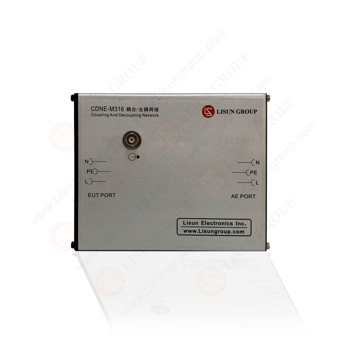
The front panel of the CDNE (Coupling and Decoupling Network) instrument connects to the device under test (EUT); see Figures 3 and 4 for front-panel diagrams, and refer to the diagram on the top of the instrument for the wiring configuration.
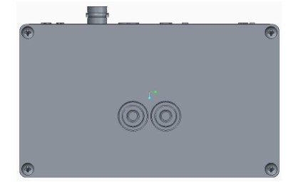
Figure 3: CDNE-M216 Front Panel
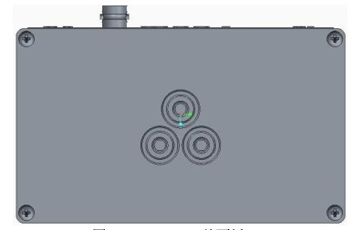
Figure 4: CDNE-M316 Front Panel
Caution: Never connect PE, N, and L incorrectly; otherwise, it may cause damage to the instrument or even result in serious injury or death!
4.2 Rear Panel of the Instrument
The rear panel of the CDNE (Coupling and Decoupling Network) instrument is connected to an external power supply. This power supply is fed into the instrument through the rear panel, passes through the Coupling and Decoupling Network, and is then output through the front panel, ultimately supplying power to the device under test.
See Figures 5 and 6 for the rear panel diagrams; see the diagram on the top of the instrument for the wiring configuration.
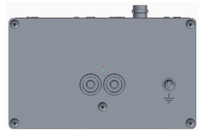
Figure 5: Rear Panel of the CDNE-M216
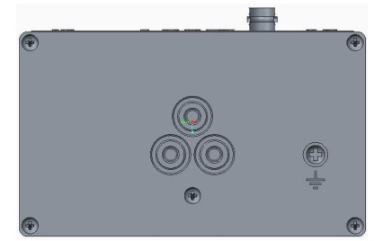
Figure 6: Rear Panel of the CDNE-M316
Caution: Never connect PE, N, and L incorrectly; otherwise, it may cause damage to the instrument or even result in serious injury or death!
The ground terminal on the rear panel of the CDNE network should be connected to the reference ground using a thick wire to ensure a reliable connection.
4.3 Instrument Operation Procedures
Warning:
Since this instrument is essentially a passive Coupling and Decoupling Network, you must strictly follow these operating procedures during use; failure to do so may result in damage to the instrument and the equipment under test, and may cause serious personal injury!
Instructions:
First, identify the metal plane to be grounded; this metal plane must be reliably grounded;
In accordance with the relevant standards, use a thick wire to securely connect the instrument’s ground terminal to the metal grounding plane;
Verify that the external power cord connected to the rear panel of the instrument is not yet powered on;
Connect the power cord of the device under test to the corresponding PE, N, and L terminals on the instrument’s front panel in accordance with the standard requirements. If the device under test is powered by a 2-wire system, use the CDNE-M216 network; if the device under test is powered by a 3-wire system, use the CDNE-M316 network;
Connect the external power supply cables to the corresponding PE, N, and L terminals on the rear panel. If the device under test uses a 2-wire power supply, use the CDNE-M216 network; if the device under test uses a 3-wire power supply, use the CDNE-M316 network;
After verifying that the above connections are correct, apply power to the external power cord;
Connect the appropriate test equipment to the network’s RF port (signal port);
Begin normal testing operations;
After testing is complete, disconnect the test instrument from the RF port on the network;
Disconnect the external power supply;
Disconnect the power cord of the device under test from the network.
4.4 Independent Method for Measuring Radiated Disturbances from Electrical Lighting Equipment in the 30–300 MHz Frequency Range
Since CDNE is an enhanced version of CDN, the method of use is similar; we will use CDN as an example below.
According to Appendix B of GB 17743-2007, if the disturbance levels of the test equipment within the 30–300 MHz frequency range, as measured using a CDN network, meet the requirements of Table B.1, the test equipment is deemed to comply with the requirements for radiated disturbance in this frequency band as specified in Section 4.4.2 of this standard, which calls for measurement using the 10-meter method. In practice, Appendix B is an alternative test method that reduces the requirements for test equipment and the test environment.
According to the standard, measurements may be taken in an unshielded room, at a distance of more than 40 cm from conductive parts; see Figure 9 for the measurement setup.
The lighting fixture under test shall be placed on one or more non-conductive wooden blocks, each with a height of (10±0.2) cm. The wooden blocks shall be placed on a grounded metal plate, the dimensions of which shall exceed those of the lighting fixture by at least 20 cm. The lighting fixture under test is connected to the CDN network via a power cable (20 ± 10) cm in length. The cable should be (4 ± 1) cm away from the metal plate. Non-conductive supports (4 ± 0.2) cm in height shall be used. The CDN network is installed on the grounded metal plate. If the lighting fixture has control terminals, these terminals are connected to the CDN-AF2 using the same method (see IEC 61000-4-6 for the requirements of this network).
The RF signal output of the CDN is connected through a 6 dB, 50 Ω attenuator (this 6 dB attenuator is not required when using a CDNE network) to a measurement receiver equipped with a quasi-peak detector. If more than one CDN network is connected to the lighting fixture, measurements should be performed separately on each CDN network in sequence. The RF output of any CDN network not connected to the measuring equipment should be terminated with a 50-ohm resistor.
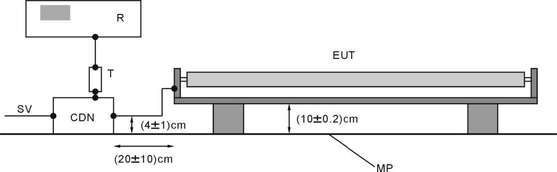
Figure 9 Experimental Setup of the CDN Network
As shown in Figure 9:
R: Measurement Receiver CDN: Coupling and Decoupling Network
SV: Power Supply EUT: Equipment Under Test
MP: Grounding Metal Plate
T: 6 dB, 50 Ω attenuator (this attenuator is not required when using a CDNE network)
5. Verification of the Voltage Division Coefficient
In accordance with the requirements of standards such as CISPR 16-1-2 (2017) and GB 6113.102-2018, the verification of the CDNE network voltage division factor is shown in Figure 10:
The test equipment used is a network analyzer or another compliant spectrum analyzer equipped with a tracking source. The RF end of the CDNE network under test is terminated with a 10 dB attenuator, which is then connected to the input of the network analyzer. The EUT end of the CDNE network is terminated with an appropriate adapter, followed by a 10 dB attenuator, and then connected to the network analyzer’s output. The AE end of the CDNE network is grounded via an appropriate adapter.
When measuring with a test instrument with a 50 Ω impedance, the RF signal is attenuated by the CDNE voltage division factor, which
The value is 20 dB, and this value should be compensated for. If the actual calibration value deviates from 20 dB, this deviation should also be compensated for.
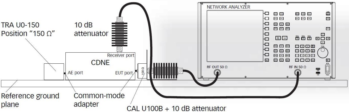
Figure 10 Verification of the Voltage Division Coefficients in the CDNE Network
LED Luminaires and LED Power Driver Test Solution
Goniophotometer System: LSG-6000, LSG-1890B
Spectroradiometer & Integrating Sphere Test System: LPCE-2, LPCE-3
LED Life Maintains a Test System in Accordance with LM-80: LEDLM-80PL
Waterproof Test for IPX5 and IPX6 Rating Testing: JL-56
Dustproof Testing Machine for IP5X and IP6X Testing: SC-015
LED Power Driver Testers: WT2080 (for the lab) and ATE-2 (for the production line)
Electrical Safety Tester: LS9955
CFL and Electronic Ballast Test Solution
Goniophotometer System: LSG-1890B
Integrating Sphere and Spectrophotometer Test System: LPCE-2
Adjustable Reference Ballast: DYJ-50HZ, HCS-105A, and DYJ-HID
Electric Ballast Tester: WT5000 (for the lab) and ATE-1 (for the production line)
Digital Torsion Meter and Multiway Life Tester: CH338 and CH316
Electrical Safety Testers: LS9923, ZRS-3H, ZY-3
EMC and EMI Test Solutions for CFL and LED Luminaires
EMI Test System: EMI-9KB or EMI-9KA
Electrostatic Discharge Simulator: ESD61000-2
EFT Immunity Measurement: EFT61000-4
Surge Generator: SG61000-5
Voltage Dips and Interruptions Generator: CSS61000-11
Ring Wave Generator: RWG61000-12

www. Lisungroup.com
Patents Filed
All Rights Reserved by Lisun Group
Subject to Change Without Notice