
 English
 中文简体
中文简体 English
 Русский
 Español
 Português
 Türkçe
 العربية
 Deutsch
 Polski
 Italiano
 Français
 한국어
한국어 ไทย
ไทย Tiếng Việt
 日本語
日本語





























Portable Color Densitometer
User's Manual
Applicable LISUN models: CD-626、CD-628、CD-630
1. Basic Understanding of Equipment
1.1 Product Overview
1.1.1 Model Classification
| LISUN Model | CD-626 | CD-628 | CD-630 |
|---|---|---|---|
| Measurement Repeatability | dE*ab ≤ 0.02 | ||
| Caliber | Φ5 mm | Φ11 mm, Φ5 mm, Φ3 mm | Φ11 mm, Φ10 mm, Φ6 mm, Φ5 mm, Φ3 mm |
| UV | Excludes | Includes | |
| Integrated physical alignment holes | Includes | ||
| NetProf Network Calibration | Excludes | Includes | |
1.1.2 Product Applications
Key Features of the CD Series Color Densitometers: These instruments integrate measurement metrics specific to printing with general colorimetric measurement capabilities, supporting print quality control parameters such as color density, dot area, dot gain, overprint ratio, print contrast, tone error, and grayscale.
CD Series Color Densitometer Additional Features: It provides more than 30 measurement parameters, including spectral reflectance, CIE-Lab, CIE-LCh, ΔE*ab, opacity, whiteness, and yellowness, and is equipped with nearly 40 evaluation light sources, meeting the color quality control needs of various industries such as printing, packaging, and coatings.
1.2 Unboxing and Checking the Contents
1.2.1 Unpacking and Visual Inspection
When unpacking the device, handle it gently to avoid scratching the outer casing with sharp tools. After unpacking, first inspect the exterior of the device to ensure there is no visible deformation or dents, and that the buttons are not damaged or loose. If you notice any abnormalities with the device or its accessories, please contact us immediately.
1.2.2 Main Unit and Accessories
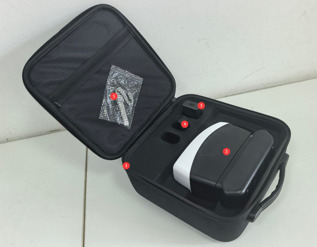
Take the CD-626 as an example; see Figure 1-1.
| Number | Note |
|---|---|
| ① | Portable Storage Box |
| ② | CD Series Color Densitometer Main Unit |
| ③ | Charger |
| ④ | USB Cable |
| ⑤ | Lanyard |
1.2.3 Downloading Electronic Documents
Download links for the digital user manual, software, warranty card, and other materials have been sent via email. Please download them promptly. If you missed the email, you can also contact us directly to request the download links again.
2. Precautions for Use
2.1 Instrument Usage Guidelines
This instrument is a precision optical testing device. Please read all safety instructions in this manual carefully before use and follow the operating procedures strictly. The company is not liable for any damage to the equipment or personal injury resulting from improper operation, and such incidents are not covered by the warranty.
Users are prohibited from disassembling the instrument housing on their own. Unauthorized disassembly may allow dust and metal debris to enter the interior, resulting in optical contamination and electrical short circuits.
Avoid violent shaking, drops, and compression by heavy objects. Do not allow liquids to splash onto the instrument’s surface or into the measuring orifice.
2.2 Battery Safety
The device is equipped with a built-in lithium battery. Do not disassemble, crush, strike, or puncture the battery. Do not expose the battery to open flames or high temperatures, as this may cause the battery to explode or catch fire.
If the instrument is fully charged but will not be used for an extended period, disconnect it from the external power source promptly to prevent overcharging, which could damage the battery or pose a safety hazard.
During daily use, charging the device when the battery level is around 20% will help extend its battery life.
If the device will be left unused for an extended period, recharge it to about 50% every two weeks to prevent permanent damage caused by the battery being completely discharged.
2.4 Environmental Requirements
Recommended operating conditions: Temperature around 20°C, standard atmospheric pressure, relative humidity 50%–70% RH.
Avoid using or storing the device in damp environments, areas with strong electromagnetic interference, direct sunlight, or high-dust environments.
Do not use this instrument in environments containing flammable or explosive gases or dust, to prevent explosions or fires.
2.5 Other
For matters not covered in this manual, please proceed with caution or contact us.
3. Equipment Overview
3.1 Main Components of the Instrument
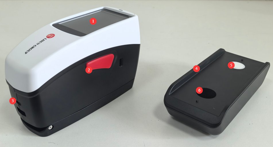
See Figure 3-1.
| Number | Note |
|---|---|
| ① | Touchscreen |
| ② | Buttons. Press briefly for 1 second to turn on the device; press and hold for 3 seconds to turn it off; when the screen is off, press briefly to turn it on. |
| ③ | USB port |
| ④ | Magnetic Base |
| ⑤ | White Calibration Module |
| ⑥ | Black Calibration Module |
3.2 Measurement Port Construction
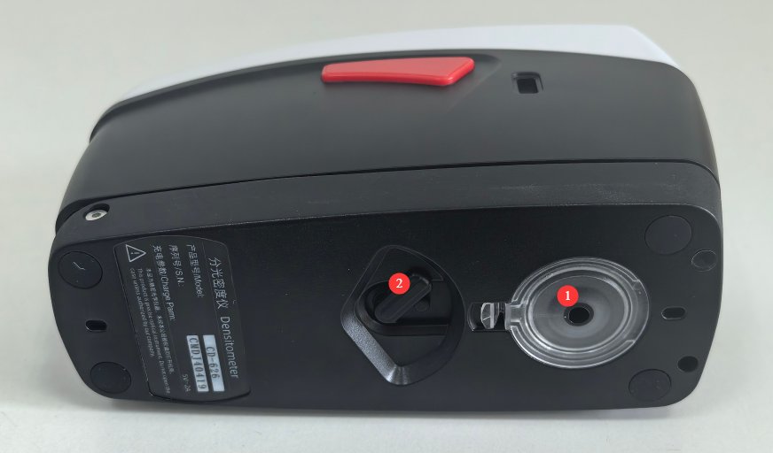
See Figure 3-2.
| Number | Note |
|---|---|
| ① | Measurement diameter, interchangeable |
| ② | The instrument is set to “press to measure” by default. Press and release the lever to lock or unlock the measuring aperture. |
3.3 Other
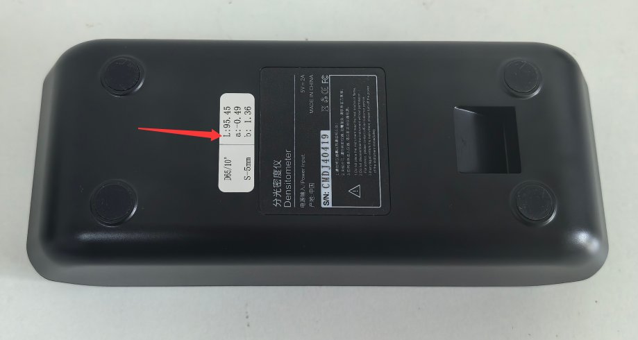
As shown in Figure 3-3, the standard color values for the white calibration module are marked on the back of the magnetic base. By measuring the whiteboard and comparing the results to the standard values, you can verify the instrument’s measurement accuracy.
4. Equipment Operation
4.1 Power-On Calibration
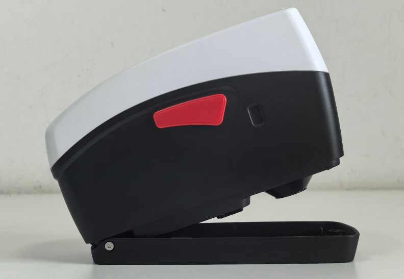
The device must be recalibrated before its first use or after being idle for more than 8 hours. Turn on the device and remove it from the magnetic base. Refer to Section 3.2 to press and slide the release lever to open the measurement aperture, as shown in Figure 4-1.
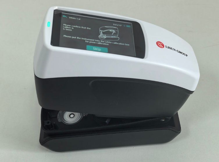
The touchscreen prompts that white calibration must be performed first. Please place the instrument back on the magnetic base and align the measurement aperture with the white calibration module, as shown in Figure 4-2.
Press the device; when the indicator light turns red, the device is active. When the indicator light returns to green, you may release the device. See Figures 4-3 and 4-4.
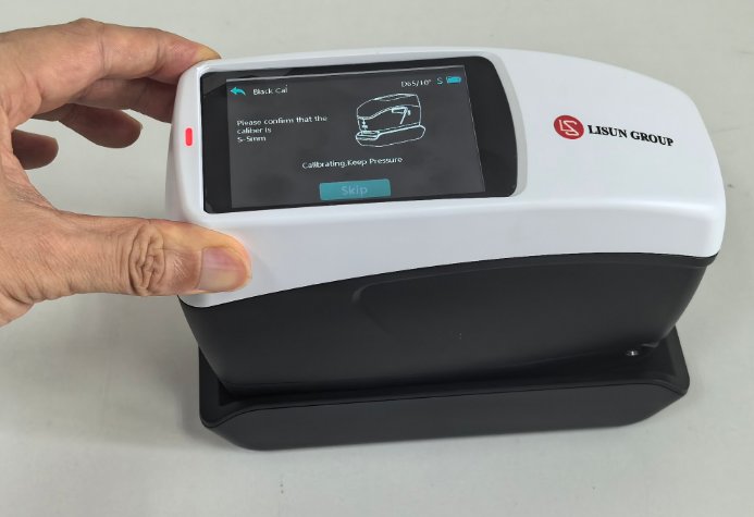
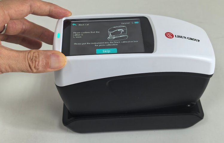
Following the instructions on the touchscreen, align the measurement aperture with the black calibration template, and perform the black calibration using the same method.
4.2 Measurement of Object Color
4.2.1 Measurement of Reference Standards
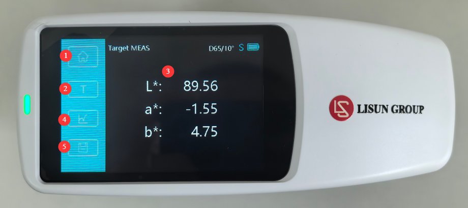
The instrument’s initial screen is the CIE-Lab color measurement screen, as shown in Figures 4 and 5.
| Number | Note |
|---|---|
| ① | Click to go to the main menu |
| ② | T: Standard Sample Measurement Interface |
| ③ | Place the measuring orifice directly against the reference sample, press down, and record the reference sample data. |
| ④ | Click to display the color spectrum of the current object |
| ⑤ | Click to save the current standard sample data to the instrument |
4.2.2 Sample Measurement
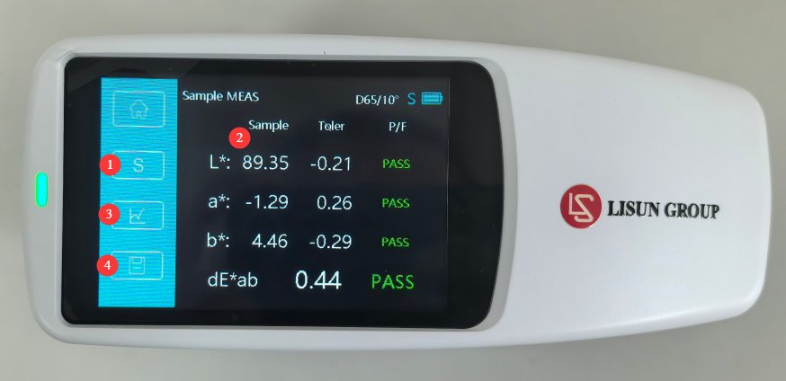
See Figures 4–6.
| Number | Note |
|---|---|
| ① | Click the “T” button to switch to the “S” screen, which is the sample measurement screen. |
| ② | Place the measuring aperture directly against the sample, press it down, and measure the sample data; the display will show the difference between the sample data and the reference standard data, as well as whether the sample passes the test. |
| ③ | Click to view the sample color spectrum. |
| ④ | Click to save the current sample data to the instrument |
4.3 Color Density Measurement
4.3.1 Accessing the Color Density Measurement Interface
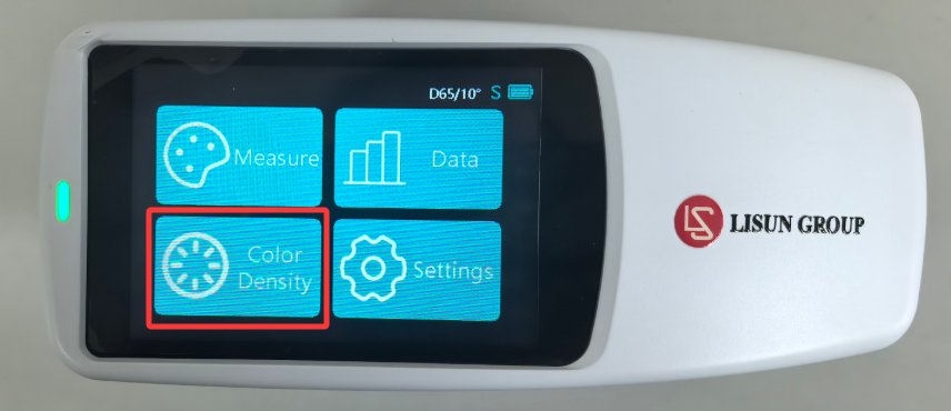
Go to the main menu and tap “Color Density” to access the color density measurement screen, as shown in Figure 4-7.
4.3.2 Introduction to the Color Density Measurement Interface
4.3.2.1 Measurement of Reference Standards
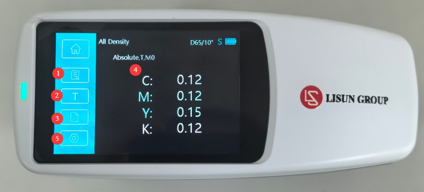
See Figures 4–8.
| Number | Note |
|---|---|
| ① | Color Density Selection |
| ② | T: Standard Sample Measurement Interface |
| ③ | Based on the density reference white settings, click here to measure the white paper swatch. |
| ④ | Place the measuring orifice directly against the standard sample, press it down, and measure the standard sample data. |
| ⑤ | Color Density Settings |
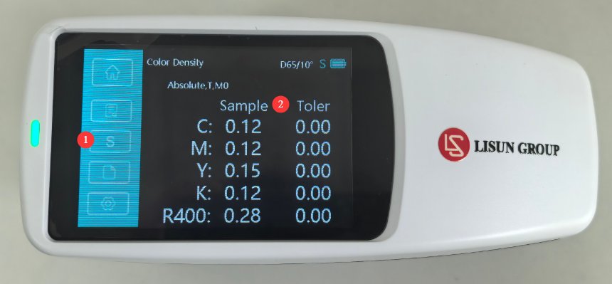
4.3.2.2 Sample Measurement
See Figures 4–9.
| Number | Note |
|---|---|
| ① | Click the “T” button to switch to “S,” which is the sample measurement interface. |
| ② | Place the measuring aperture directly against the sample, press it down, and measure the sample data; the difference between the sample data and the reference sample data will be displayed simultaneously. |
4.3.3 Introduction to Other Interfaces for Color Density
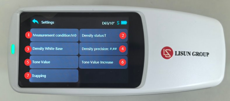
4.3.3.1 Color Density Settings Interface
See Figure 4-10.
| Number | Note |
|---|---|
| ① Measurement Conditions | M0: No filter; M1: (D50); M2: (UVC)—UV-blocking filter; M3: (Pol)—polarizing filter |
| ② Density State | Status T, E, I, A, M |
| ③ Density Reference White | Used to set paper or absolute density values for various density functions. If “Relative to Paper” is selected, all subsequent measurements refer only to the printed ink layer and do not include the paper’s color effect; if “Absolute Density” is selected, the measurements include the paper’s effect in addition to the printed ink layer. |
| ④ Density Accuracy | Used to select the display precision for density values: two decimal places or three decimal places |
| ⑤ Branch Area | A method for determining the absolute ink coverage (%) of a tone or halftone patch by comparing its density value to known density values of 0% (paper/substrate) and 100% (solid color patch). Options include: the Murray-Davis coefficient, the Uhl-Nielsen coefficient, and SCTV (ISO 20654). |
| ⑥ Increased branch size | Set the percentages for up to three color blocks. Typically, these are 25%, 50%, and 75%, but you can also enter custom values. |
| ⑦ Overprinting | You can set overprinting formulas; the available options are: Preucil, Brunner, and Ritz. |
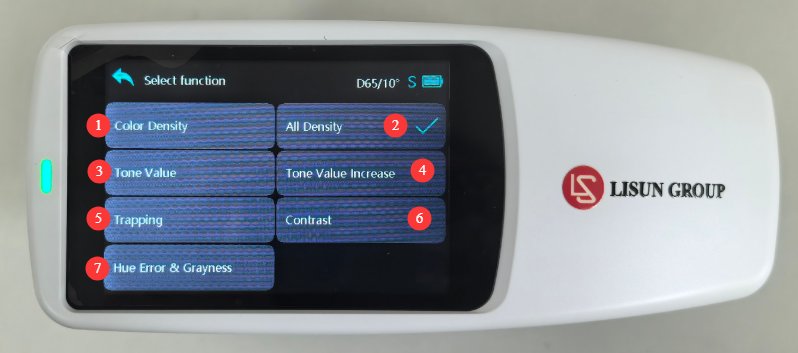
4.3.3.2 Color Density Selection Interface
See Figure 4-11.
| Number | Note |
|---|---|
| ① | Color Density |
| ② | All Color Densities |
| ③ | Branch Area |
| ④ | Increased Branch Size |
| ⑤ | Overprint |
| ⑥ | Print Contrast |
| ⑦ | Color Deviation and Grayscale |
4.4 Overview of Other Touchscreen Interface Features
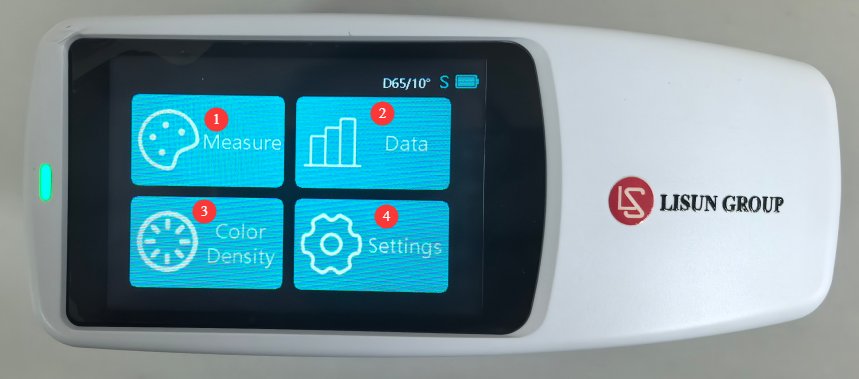
4.4.1 Main Interface
See Figure 4-12.
| Number | Note |
|---|---|
| ① | Go to the object color measurement screen |
| ② | View Saved Object Color Measurement Data |
| ③ | Go to the color density measurement screen |
| ④ | System Settings |
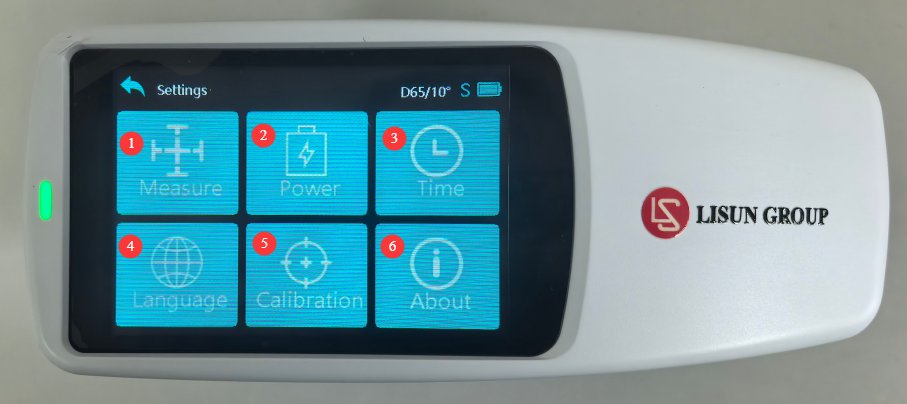
4.4.2 System Settings Screen
See Figure 4-13.
| Number | Note |
|---|---|
| ① | Measurement Settings |
| ② | Power Management |
| ③ | Time Settings |
| ④ | Language Selection |
| ⑤ | To manually trigger calibration, follow the same steps as in Section 4.1. |
| ⑥ | Product Information |
5. Using the Software
5.1 Online
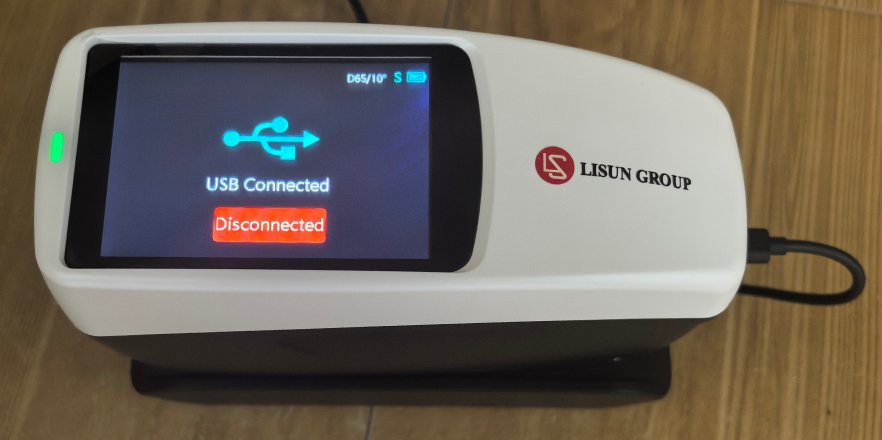
Connect the instrument to the computer using the standard USB cable; the instrument’s interface will display “USB Connected,” as shown in Figure 5-1.
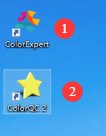
See Figure 5-2 for the software icon.
| Number | Note |
|---|---|
| ① | This is paid color management software; you don’t have to use it. |
| ② | Double-click to open this software. Once it opens, it will automatically connect to the internet. |
5.2 Software Operation
5.2.1 Introduction to the Software’s Main Interface
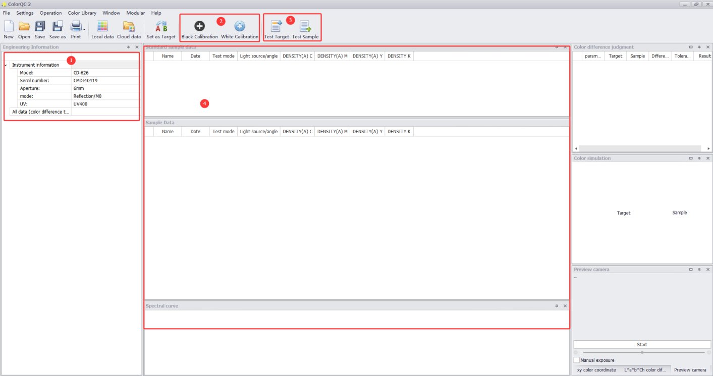
See Figure 5-3.
| Number | Note |
|---|---|
| ① | Information on Automatic Communication Equipment |
| ② | The calibration procedure follows the same steps as described in Section 4.1. When using software control, there is no need to release the measurement aperture. |
| ③ | Testing procedures are the same as those described in sections 4.2 and 4.3.2. When using software control, there is no need to release the measurement aperture. |
| ④ | Test Results Section |
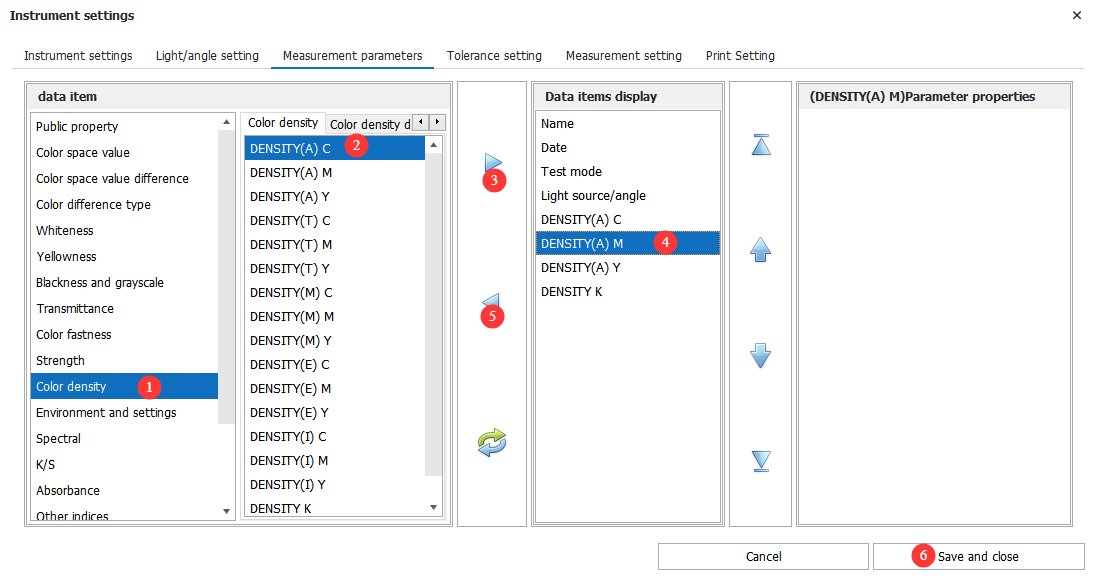
5.2.2 Test Parameter Options
Click “Settings” > “Display Parameters” to modify the test parameters, as shown in Figure 5-4.
| Number | Note |
|---|---|
| ① | Select Color Density |
| ② | Select the parameters you want to display |
| ③ | Click the right arrow |
| ④ | You can then add the corresponding parameter. To delete the parameter, select it. |
| ⑤ | Click the left-pointing arrow to delete it. |
| ⑥ | Once you’re done, click “Save” and exit. |
5.2.3 Print Parameter Options
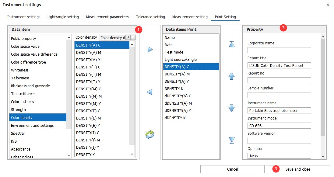
Click “Settings” > “Print Settings” to modify the test parameters, as shown in Figure 5-5.
| Number | Note |
|---|---|
| ① | Use the same method as in 5.2.2 to add or remove display parameters. |
| ② | You can enter relevant sample and test information |
| ③ | Click Save and Exit |
5.2.4 Test and Print the Report
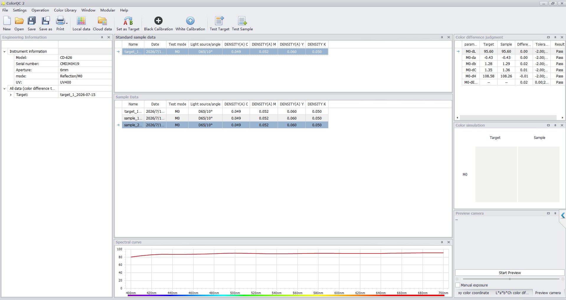
The test results are shown in Figures 5 and 6.
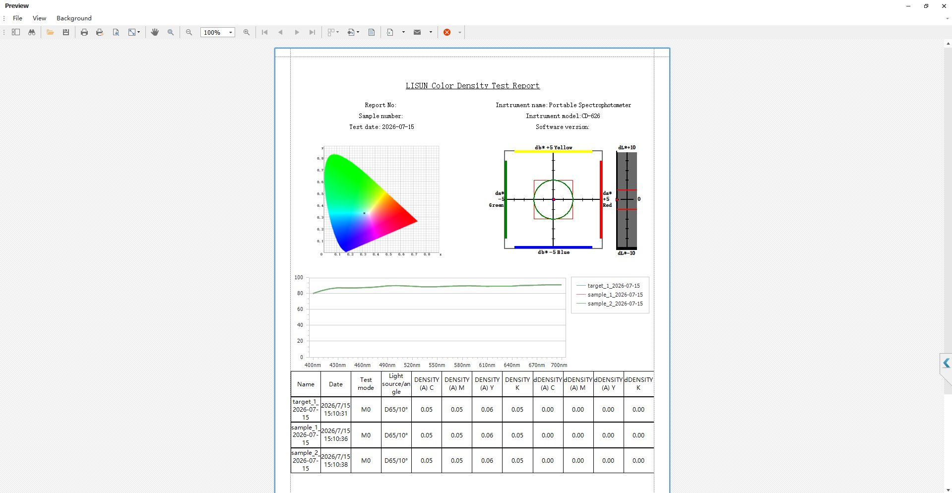
Click “Print” > “Print graphics” to preview and print the test report, as shown in Figure 5-7.
6. Daily Maintenance and Care of Equipment
6.1 Daily Cleaning and Maintenance
6.1.1 Cleaning the Aircraft
After daily use, wipe the surface of the device with a clean, soft, dry cloth to remove dust. If there are stains, gently wipe them with a cloth dampened with a small amount of water; do not use organic solvents. Ensure the device is turned off before cleaning to prevent liquid from entering the ports or the interior.
6.1.2 Cleaning the Measurement Port
Before and after each use, check the measurement aperture for dust or ink stains; gently wipe the measurement aperture with a lint-free cotton swab or a special cleaning cloth.
6.1.3 Cleaning the Touchscreen
Gently wipe the screen surface with a soft, lint-free cloth; avoid scratching the screen with sharp objects; do not wipe the screen directly with corrosive liquids.
6.2 Calibration Module Maintenance
The calibration module is a precision optical standard and serves as a reference for measurement accuracy; it must be stored properly. Avoid allowing sharp objects to come into contact with the working surface of the calibration module, and prevent it from becoming contaminated. Do not expose the calibration whiteboard to strong light for extended periods. Periodically clean the working surface of the white calibration module gently with a lint-free cloth dampened with a small amount of anhydrous alcohol; before calibration, remove any dust from the surface of the white calibration module to ensure the accuracy of the calibration reference.
6.3 Calibration Interval Requirements
To ensure the instrument’s measurement accuracy and operational reliability, it is recommended that it be sent periodically to a qualified third-party metrology laboratory for calibration. The recommended calibration interval is 12 months. The specific calibration interval may be determined by the user based on frequency of use, environmental conditions, and quality system requirements.
7. Troubleshooting and Resolving Common Problems
| Fault Symptoms | Possible Causes | Procedure |
|---|---|---|
| No response when pressing the power button; the device shuts down automatically after turning on | The battery is dead | Plug in the power adapter and charge the device for 30 minutes, then try turning it on again; if it still won’t turn on, the battery is damaged. |
| Unable to charge | Did not use original parts | Please use the original charger and USB cable; if the device still won’t charge, the battery is damaged. |
| The touchscreen is unresponsive | There are smudges on the screen, and the system freezes | Try again after cleaning the screen; press and hold the power button to force a shutdown, then restart the device. |
| Calibration Failed | The calibration module is dirty or contains foreign objects | Clean the white calibration module, check the black calibration module for foreign objects, and then recalibrate. |
| The color density values are significantly low | Incorrect white density reference setting; ink layer not dry | Check to see if the device has been accidentally set to absolute density mode; wait until the ink is completely dry before taking a measurement. |
| No response when connecting to a computer via USB | Did not use original parts | Please use the original USB cable. |
Appendix: Glossary of Technical Terms
A.1 Terms Related to Chromaticity
CIE-Lab: A uniform color space recommended by the International Commission on Illumination (CIE), where L represents lightness, a represents the red-green axis, and b* represents the yellow-blue axis.
ΔE*ab: The total color difference value based on the Lab color space; the higher the value, the more pronounced the color difference.
ΔE*00: The CIE 2000 color difference formula, which more closely matches human visual perception, is currently the mainstream formula for evaluating color difference.
D65 light source: A standard light source that simulates average daylight, with a color temperature of 6504 K; it is the most commonly used evaluation light source.
D50 Light Source: Simulates north-facing indoor daylight with a color temperature of 5003 K; commonly used for proofing in the printing industry
2°/10° field of view: Standard observer angles, corresponding to narrow-field and wide-field observation conditions, respectively
A.2 Terminology Related to Print Density
Color Density: Indicates the degree to which ink absorbs light; the higher the value, the thicker the ink layer and the darker the color.
Status T: A standard for density response commonly used in the North American printing industry
Status E: A density response standard commonly used in the European printing industry
Screen Area: The percentage of the area in a halftone patch occupied by screen dots
Dot Gain (TVI): The difference between the actual dot area after printing and the theoretical dot area on the film; it is a key indicator in print quality control.
Overprint Efficiency: The color rendering efficiency achieved after multiple ink colors are overprinted; it reflects the quality of the overprinting result.
Printing Contrast: The relative difference between solid density and shadow-tone dot density, which reflects the ability to reproduce shadow-tone gradations
Color Deviation: The degree of deviation between the actual hue of the ink and the ideal hue, reflecting the ink’s purity
Gray Value: The proportion of neutral gray components in colored ink; the higher the gray value, the less saturated the color.
SCTV: The method for calculating spot color tonal values specified in the ISO 20654 standard is applicable to spot color dot measurements.
For more information on how to use the PC software or its advanced features, please refer to the accompanying ColorExpert software user manual.